I had a first look at the rabbit so to say the other day for my hands free mobile microphone. I decided to change tack on the approach and had another troll on the internet for something I could possibly modify. Took a while to find but I eventually came across a commercially produced hands free job that could be a contender. They are made in China and configured in their connections for the mainstream transceiver brands. Another half hour on Ebay and I managed to find a UK stockist so I ordered one configured for Kenwood transceivers. The basic setup of microphone and some kind of PTT arrangement remains the same, only the configuration of the wiring to the transceiver microphone plug varies between brands.
The common denominator across all three variants of the kit is that they all use a standard RJ45 connection to the transceiver, use of this connector has become pretty standard on all amateur equipment of the last few years. My main Yaesu transceiver uses the same connector. RJ45 is the standard connector used on CAT5 and CAT6 network cabling. The RJ45 plugs are 8 pole crimp on connectors and I have all the necessary crimping and punch down tools to make whatever arrangement I need.
I will be able to use some of the components that I originally ordered so all is not wasted there. I have made a start and taken a few pictures which I will put up tomorrow.
Amateur Radio Homebrew (Shack Culture)
-
PanBiker

- Site Administrator

- Posts: 16447
- Joined: 23 Jan 2012, 13:07
- Location: Barnoldswick - In the West Riding of Yorkshire, always was, always will be.
Re: Amateur Radio Homebrew (Shack Culture)
Right, so this is what I found:
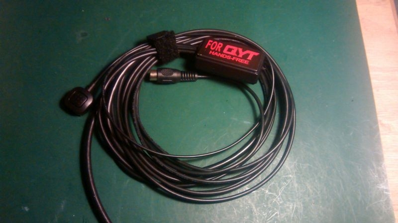
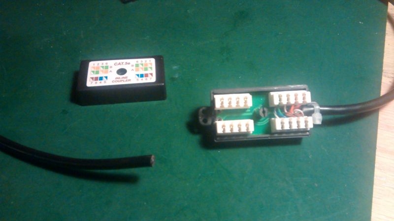
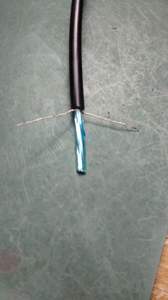
It's coiled up but you can see that it has a phono connector that is what the goose neck microphone plugs into. You can also see the small PTT switch, this is Velcro backed and you use the Velcro strip shown wrapped round the leads to attach it in a conveniently accessible position. I will confirm when I test it but I think the switch is only a momentary type rather than a latching variety. If this is the case I will swap it out for the latching one I bought. You can also see that all the interconnections from the various cables are pulled together in a small encased common connector block. The lead heading out of shot has the RJ45 connection for the transceiver and it is this lead that needs it's connections changing to match my transceiver.
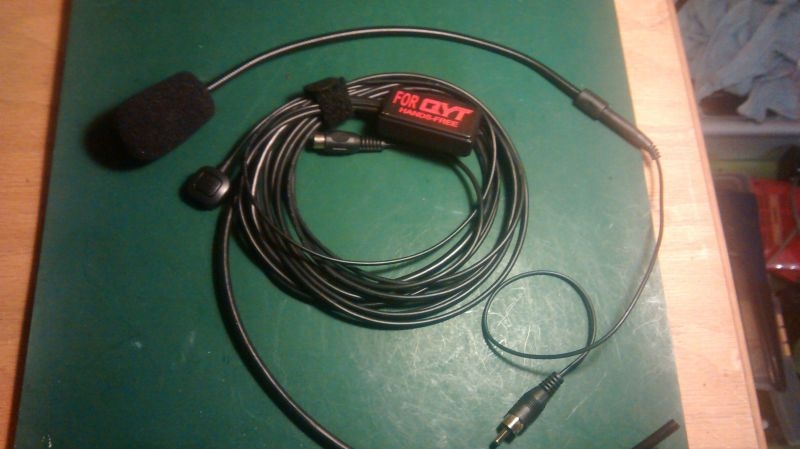
Here it is with the goose neck microphone. you can also see the different diameter leads, hence the need for the connection block to connect all the different types. The lead to the microphone will be single miniature coax. The lead to the PTT switch round twin core and I know the lead to the transceiver is six core screened and is also foil wrapped.
First job was to cut the existing RJ45 plug off to determine what colours were used for each of the connections. five of the six conductors are actually used along with the screening cable. We have connections for microphone, PTT, Up, Down and a positive (+VE) feed to power the electret microphone. The screening cable is split into two but provides a common ground and return path for the functions, the wrapped foil screen is not used in the connections but provides an overall shield against interference pickup along the lead.
I first tried crimping a replacement RJ45 plug (suitably rewired) onto the existing cable but ran into a problem that the cable used is not the same spec as CAT 5 cable, the individual conductors in the shielded cable are thinner and I had to split the screening to provide two ground connections. It was clear that another solution would be required.
The up/down leads if used give you the ability to change channels on the transceiver. That would require two other switches or some rocker switch kind of arrangement and is not really necessary. All I actually need is the mic and its associated power feed and ground and the PTT switch line to control the transceiver between receive and transmit.
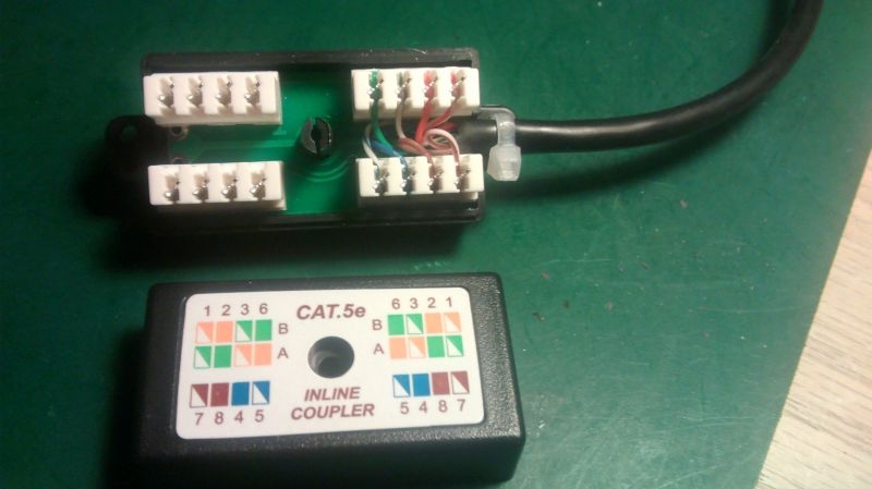
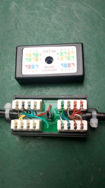
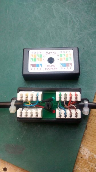
My design committee in my head when thinking about my own design had already decided that I would use a common connector type arrangement to connect all the various leads. I had also decided that as the transceiver uses a standard RJ45 plug for its input connections I would use the CAT 5 or 6 cable that it was designed for. This also gave the opportunity to use a common connection arrangement by way of a CAT 5 jointing block as shown in the photo. This has two banks of IDC connectors arranged as 2 x 4 and connected 1:1, there are two wiring conventions used in multi-wire networking T568A and T568B, you can see that this jointing block can cater for both regimes, T568B is used as standard in straight through patch cabling. The colour coding for individual conductors is agreed internationally to maintain network integrity.
What I have done here is utilised a standard CAT 5 patch lead which are all wired 1:1. I have chopped the plug off one end, stripped back the outer jacket and punched down the conductors into their matching positions on the connector blocks. I have punched down all eight leads although I will only be using five of them.
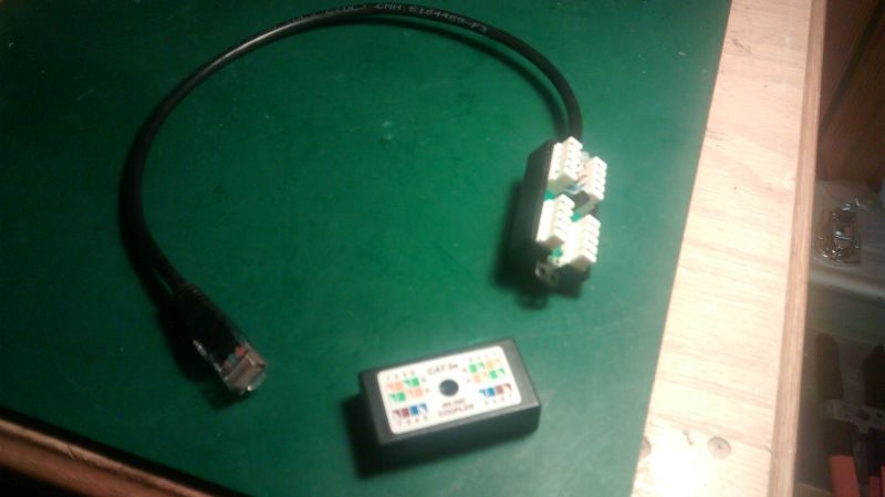
Here's the arrangement, you can see I now have short CAT 5 lead attached to the inline coupler.
I know how these connections are assigned on the transceiver. I also know the colours of the relative conductors from the hands free mic arrangement. It should be straightforward enough to reassign the connections where I want them in the block. I had intended to encapsulate the connector block in potting compound. I bought a self mixing type to do the job. Might as well use it once I have tested that all is OK.
That's as far as I have got at the moment. I said i would put some pictures up of the new mobile transceiver so here they are:
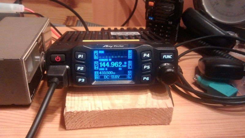
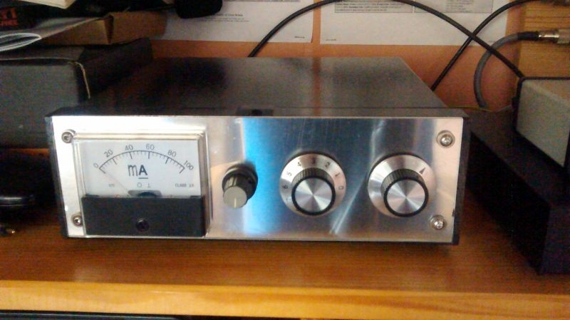
Here is a front view of the transceiver. It has dual watch facilities so you can see that it is currently tuned to 144.96250 MHz which is the frequency of a local 2 Meter gateway repeater and also 433.500 MHz which is the calling channel on 70cms The buttons on the transceiver are multifunction and are used in conjunction with the function (FUNC) button and the main VFO control below to access the various menus and functions of the transceiver. The microphone connection is at the lower left with the power on/off button above. You can judge the size of the unit by my hand held transceiver behind and my Small SWR meter on the left.
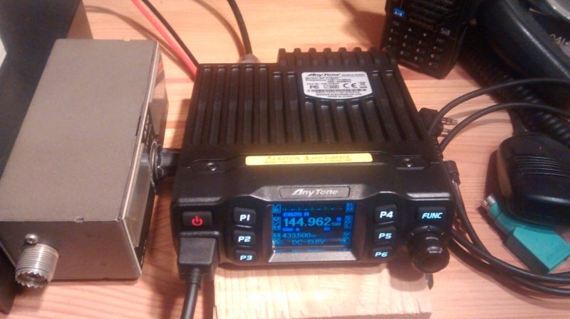
Here is another view from slightly above you can see that the unit is basically a miniature transceiver integrated with a quite large heatsink. The transceiver offer three power levels of 5/15 and 25W so it will run reasonably warm on high power so needs the heatsink. The overall dimensions of the unit are only 124mm (w) x 163mm (d) x 39mm (h) which in real money is 4.8" x 6.4" x 1.5".
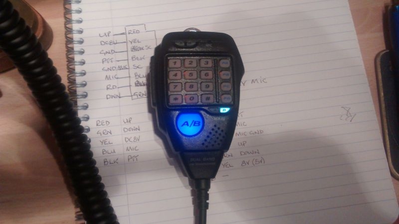
Here is the hand held DTMF (Dual Tone Multi Frequency) Microphone that it is supplied with. PTT switch on the left, Up/Down switches on the right. VFO A/B switching and the keypad for actioning DTMF access tones as required by some types of repeaters.
It's coiled up but you can see that it has a phono connector that is what the goose neck microphone plugs into. You can also see the small PTT switch, this is Velcro backed and you use the Velcro strip shown wrapped round the leads to attach it in a conveniently accessible position. I will confirm when I test it but I think the switch is only a momentary type rather than a latching variety. If this is the case I will swap it out for the latching one I bought. You can also see that all the interconnections from the various cables are pulled together in a small encased common connector block. The lead heading out of shot has the RJ45 connection for the transceiver and it is this lead that needs it's connections changing to match my transceiver.
Here it is with the goose neck microphone. you can also see the different diameter leads, hence the need for the connection block to connect all the different types. The lead to the microphone will be single miniature coax. The lead to the PTT switch round twin core and I know the lead to the transceiver is six core screened and is also foil wrapped.
First job was to cut the existing RJ45 plug off to determine what colours were used for each of the connections. five of the six conductors are actually used along with the screening cable. We have connections for microphone, PTT, Up, Down and a positive (+VE) feed to power the electret microphone. The screening cable is split into two but provides a common ground and return path for the functions, the wrapped foil screen is not used in the connections but provides an overall shield against interference pickup along the lead.
I first tried crimping a replacement RJ45 plug (suitably rewired) onto the existing cable but ran into a problem that the cable used is not the same spec as CAT 5 cable, the individual conductors in the shielded cable are thinner and I had to split the screening to provide two ground connections. It was clear that another solution would be required.
The up/down leads if used give you the ability to change channels on the transceiver. That would require two other switches or some rocker switch kind of arrangement and is not really necessary. All I actually need is the mic and its associated power feed and ground and the PTT switch line to control the transceiver between receive and transmit.
My design committee in my head when thinking about my own design had already decided that I would use a common connector type arrangement to connect all the various leads. I had also decided that as the transceiver uses a standard RJ45 plug for its input connections I would use the CAT 5 or 6 cable that it was designed for. This also gave the opportunity to use a common connection arrangement by way of a CAT 5 jointing block as shown in the photo. This has two banks of IDC connectors arranged as 2 x 4 and connected 1:1, there are two wiring conventions used in multi-wire networking T568A and T568B, you can see that this jointing block can cater for both regimes, T568B is used as standard in straight through patch cabling. The colour coding for individual conductors is agreed internationally to maintain network integrity.
What I have done here is utilised a standard CAT 5 patch lead which are all wired 1:1. I have chopped the plug off one end, stripped back the outer jacket and punched down the conductors into their matching positions on the connector blocks. I have punched down all eight leads although I will only be using five of them.
Here's the arrangement, you can see I now have short CAT 5 lead attached to the inline coupler.
I know how these connections are assigned on the transceiver. I also know the colours of the relative conductors from the hands free mic arrangement. It should be straightforward enough to reassign the connections where I want them in the block. I had intended to encapsulate the connector block in potting compound. I bought a self mixing type to do the job. Might as well use it once I have tested that all is OK.
That's as far as I have got at the moment. I said i would put some pictures up of the new mobile transceiver so here they are:
Here is a front view of the transceiver. It has dual watch facilities so you can see that it is currently tuned to 144.96250 MHz which is the frequency of a local 2 Meter gateway repeater and also 433.500 MHz which is the calling channel on 70cms The buttons on the transceiver are multifunction and are used in conjunction with the function (FUNC) button and the main VFO control below to access the various menus and functions of the transceiver. The microphone connection is at the lower left with the power on/off button above. You can judge the size of the unit by my hand held transceiver behind and my Small SWR meter on the left.
Here is another view from slightly above you can see that the unit is basically a miniature transceiver integrated with a quite large heatsink. The transceiver offer three power levels of 5/15 and 25W so it will run reasonably warm on high power so needs the heatsink. The overall dimensions of the unit are only 124mm (w) x 163mm (d) x 39mm (h) which in real money is 4.8" x 6.4" x 1.5".
Here is the hand held DTMF (Dual Tone Multi Frequency) Microphone that it is supplied with. PTT switch on the left, Up/Down switches on the right. VFO A/B switching and the keypad for actioning DTMF access tones as required by some types of repeaters.
Ian
-
Stanley

- Global Moderator

- Posts: 90301
- Joined: 23 Jan 2012, 12:01
- Location: Barnoldswick. Nearer to Heaven than Gloria.
Re: Amateur Radio Homebrew (Shack Culture)
All Chinese to me Ian but I know neat and tidy when I see it. Nice work.
Stanley Challenger Graham
Stanley's View
scg1936 at talktalk.net
"Beware of certitude" (Jimmy Reid)
The floggings will continue until morale improves!
Stanley's View
scg1936 at talktalk.net
"Beware of certitude" (Jimmy Reid)
The floggings will continue until morale improves!
-
PanBiker
- Site Administrator
- Posts: 16447
- Joined: 23 Jan 2012, 13:07
- Location: Barnoldswick - In the West Riding of Yorkshire, always was, always will be.
Re: Amateur Radio Homebrew (Shack Culture)
Furthered the microphone project a bit more this afternoon. Next job is to terminate the five core and screen cable from the Mic and PTT to the CAT 5 joint block. First job prepare the cable.
Cable with outer jacket removed, I have split the outer screening into two and solder tinned it to beef it up a bit You can see the foil wrapping that encloses the inner conductors.
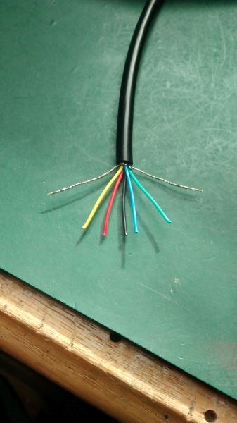
I have stripped the foil wrapping back and you can see the five conductors I will only need three of these as I am not using the up/down feature of the transceiver. This would require either an extra rocker or two extra individual momentary switches.
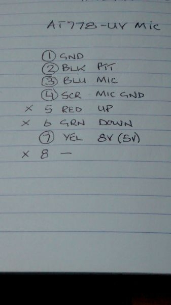
Here is my crib that I copied from the manual for the microphone socket. You can see that I don't need the red or green leads. I terminated the two ground connections from the screening cable first then the Black for the PTT, Blue for the Microphone and finally the Yellow which will provide 5v from the transceiver to power the electret insert of the Microphone. It's also marked as 8v as that is what a Kenwood transceiver that the mic was originally cabled for would provide. The difference in voltage is negligible and is within the range of the voltage requirement of the microphone.
Here is the connector with the conductors terminated according to my crib. At this point it is time for a test so I hooked up the microphone via its phone connector and plugged the RJ45 into the transceiver. So far so good, transceiver still in receive as expected, pressing the PTT switch should switch the transceiver to transmit but NOTHING, no effect whatsoever. Unplug again and go over my connections, all fine according to the crib. I went back to cross check with the manual and found the note in very small type that said that the view of the diagram given was looking INTO the socket. I actually followed the pin numbers given which, if looking into the RJ45 socket are the wrong way round! Grrrr
Not uncommon to find odd errors in the manuals for Chinese equipment.
Back on the bench pull out the conductors, chop a bit of cable back and start again preparing the cable. Same setup, still need the two ground connections and the Black, Blue and Yellow. I modified this slightly by insulating the Red and Green leads with a short length of heat shrink on each one.
Re-connected the opposite way round so 1 is 8, 2,7 etc..
Reconnected to the transceiver and the PTT now works correctly. The switch provided is indeed a simple momentary type which is not much good for mobile use as it would require you holding it closed all the time you were transmitting which would take up one hand. I will swap this out for the latching push button that I originally ordered. I have not checked the microphone yet. I need to go back up to my station tonight and swap a few antenna leads to get the mobile transceiver onto my main tri-band vertical antenna. There should be one or two other amateurs on the band tonight so I can ask for a proper report. I will post again after I have used it on air.
Cable with outer jacket removed, I have split the outer screening into two and solder tinned it to beef it up a bit You can see the foil wrapping that encloses the inner conductors.
I have stripped the foil wrapping back and you can see the five conductors I will only need three of these as I am not using the up/down feature of the transceiver. This would require either an extra rocker or two extra individual momentary switches.
Here is my crib that I copied from the manual for the microphone socket. You can see that I don't need the red or green leads. I terminated the two ground connections from the screening cable first then the Black for the PTT, Blue for the Microphone and finally the Yellow which will provide 5v from the transceiver to power the electret insert of the Microphone. It's also marked as 8v as that is what a Kenwood transceiver that the mic was originally cabled for would provide. The difference in voltage is negligible and is within the range of the voltage requirement of the microphone.
Here is the connector with the conductors terminated according to my crib. At this point it is time for a test so I hooked up the microphone via its phone connector and plugged the RJ45 into the transceiver. So far so good, transceiver still in receive as expected, pressing the PTT switch should switch the transceiver to transmit but NOTHING, no effect whatsoever. Unplug again and go over my connections, all fine according to the crib. I went back to cross check with the manual and found the note in very small type that said that the view of the diagram given was looking INTO the socket. I actually followed the pin numbers given which, if looking into the RJ45 socket are the wrong way round! Grrrr
Not uncommon to find odd errors in the manuals for Chinese equipment.
Back on the bench pull out the conductors, chop a bit of cable back and start again preparing the cable. Same setup, still need the two ground connections and the Black, Blue and Yellow. I modified this slightly by insulating the Red and Green leads with a short length of heat shrink on each one.
Re-connected the opposite way round so 1 is 8, 2,7 etc..
Reconnected to the transceiver and the PTT now works correctly. The switch provided is indeed a simple momentary type which is not much good for mobile use as it would require you holding it closed all the time you were transmitting which would take up one hand. I will swap this out for the latching push button that I originally ordered. I have not checked the microphone yet. I need to go back up to my station tonight and swap a few antenna leads to get the mobile transceiver onto my main tri-band vertical antenna. There should be one or two other amateurs on the band tonight so I can ask for a proper report. I will post again after I have used it on air.
Ian
-
PanBiker
- Site Administrator
- Posts: 16447
- Joined: 23 Jan 2012, 13:07
- Location: Barnoldswick - In the West Riding of Yorkshire, always was, always will be.
Re: Amateur Radio Homebrew (Shack Culture)
Later, tried the mobile microphone on air tonight and got positive reports from a couple of radio amateur friends, Alan who is just down the bottom of Gisburn Road and Chris who lives in Thornton in Craven. Both gave me Q5 which means good audio strength and tone, natural sounding so that is good enough for me. Just need to address the next stage which is encapsulating the jointing block in potting compound. So next task is to find a suitable container to suspend the block in with enough clearance all round.
Ian

Re: Amateur Radio Homebrew (Shack Culture)
`How amateur radio is connecting people during lockdown' BBC
`Amateur radio use in the UK has seen a "significant" rise during the coronavirus lockdown as people seek new ways of staying connected. The national body that represents users - the Radio Society of Great Britain (RSGB) - has said many people who formerly enjoyed the hobby are also returning to it...'.
`Amateur radio use in the UK has seen a "significant" rise during the coronavirus lockdown as people seek new ways of staying connected. The national body that represents users - the Radio Society of Great Britain (RSGB) - has said many people who formerly enjoyed the hobby are also returning to it...'.
Nullius in verba: On the word of no one (Motto of the Royal Society)
-
PanBiker
- Site Administrator
- Posts: 16447
- Joined: 23 Jan 2012, 13:07
- Location: Barnoldswick - In the West Riding of Yorkshire, always was, always will be.
Re: Amateur Radio Homebrew (Shack Culture)
There are a lot more active amateurs on the bands now, some returning and new licensees. We regularly have 5, 6, or 7 on our local "nets" Not quite back at the level of activity when I was first licenced but very encouraging.
The rules for obtaining a novice licence have been relaxed also. There is no practical component and the multi-choice exam is done online. You can get the syllabus and study materials online. The novice licence once attained allows access to the amateur band with low power (10w) still enough for worldwide communication. Licensees can then progress to Intermediate or the full licence as their interest and experience grows.
RSGB - Guide to becoming a UK Radio Amateur
Ian
-
Stanley
- Global Moderator
- Posts: 90301
- Joined: 23 Jan 2012, 12:01
- Location: Barnoldswick. Nearer to Heaven than Gloria.
Re: Amateur Radio Homebrew (Shack Culture)
I have a question Ian, I saw a pickup parked in Barlick yesterday with one of those big aerials with a spring incorporated in it on the roof. I always associated these with Citizen's Band. Is CB still going? Are they still going on air, "Breaker Breaker"?
Stanley Challenger Graham
Stanley's View
scg1936 at talktalk.net
"Beware of certitude" (Jimmy Reid)
The floggings will continue until morale improves!
Stanley's View
scg1936 at talktalk.net
"Beware of certitude" (Jimmy Reid)
The floggings will continue until morale improves!
-
PanBiker
- Site Administrator
- Posts: 16447
- Joined: 23 Jan 2012, 13:07
- Location: Barnoldswick - In the West Riding of Yorkshire, always was, always will be.
Re: Amateur Radio Homebrew (Shack Culture)
Yes some folk still use CB, both legal and illegal. The legal kit is licence exempt and the illegal stuff which is often amateur radio equipment of course does require a licence, and a qualification to use it.
Ian
-
Stanley
- Global Moderator
- Posts: 90301
- Joined: 23 Jan 2012, 12:01
- Location: Barnoldswick. Nearer to Heaven than Gloria.
Re: Amateur Radio Homebrew (Shack Culture)
Thanks Ian.
My mind goes back to a friend in N Carolina who was forever grabbing his mike and shouting into it but nobody ever responded to him. He had all the jargon off though, sounded just like the blokes on 'Convoy'!
My mind goes back to a friend in N Carolina who was forever grabbing his mike and shouting into it but nobody ever responded to him. He had all the jargon off though, sounded just like the blokes on 'Convoy'!
Stanley Challenger Graham
Stanley's View
scg1936 at talktalk.net
"Beware of certitude" (Jimmy Reid)
The floggings will continue until morale improves!
Stanley's View
scg1936 at talktalk.net
"Beware of certitude" (Jimmy Reid)
The floggings will continue until morale improves!
-
PanBiker
- Site Administrator
- Posts: 16447
- Joined: 23 Jan 2012, 13:07
- Location: Barnoldswick - In the West Riding of Yorkshire, always was, always will be.
Re: Amateur Radio Homebrew (Shack Culture)
My main transceiver has a general coverage receiver and I sometimes go down onto the CB frequencies to be nosy. It's only 1MHz lower, on 27MHz than the 10m (28MHz) amateur band. This is why some illegal CB operators use amateur equipment as it is much better quality than the run of the mill CB equipment. The settings on my transceiver will not let me transmit on the CB frequencies as they are "out of band" despite no licence being required for that section of the band. Restrictions were relaxed further for the CB fraternity in 2014. Previously limited to FM transmissions, they can now operate using AM and SSB modes, another reason to use amateur radio kit illegally. Not much CB activity that I can hear, unless I am listening at the wrong time. 
I can modify my transceiver quite easily to give full coverage on transmit and receive on the CB section of the spectrum but I wont bother.
I can modify my transceiver quite easily to give full coverage on transmit and receive on the CB section of the spectrum but I wont bother.
Ian

Re: Amateur Radio Homebrew (Shack Culture)
I used to use a CB when wagon driving, quite useful for 'live' traffic reports.
Kev
Stylish Fashion Icon.

Stylish Fashion Icon.

-
PanBiker
- Site Administrator
- Posts: 16447
- Joined: 23 Jan 2012, 13:07
- Location: Barnoldswick - In the West Riding of Yorkshire, always was, always will be.
Re: Amateur Radio Homebrew (Shack Culture)
I have a new small project on the go. But before I started on that I decided to revisit the ground tuner I built to address the problem of the non functioning meter. I had modified the sensing circuit for the meter as I didn't have the single coax as specified in the design. Needless to say my modification didn't work in this instance. A recent rummage in one of my storage boxes has produced enough length of a more suitable cable. I replaced my mod and put the design back to spec, guess what, it works! I only get an indication of ground current in the random length of earth wire on one band though. Thinking about this it is actually correct. I get current flow on the 17m band (18MHz). My antenna is 20M long and is therefore resonant on the multiplications or divisions of that. so 80m, 40m, 20m 10m are fully resonant so don't need a counterpoise earth so no ground current. Here is the completed unit. I cant test it fully yet as the 17M Band is generally flat at the moment but should get better over the next few years as we come out of solar minimum and start on the upward climb to maximum solar activity which of course has a massive effect on propagation on the various frequencies.
My next project is a means to an end as it is needed to effect a repair (if I can) on my matching 25W linear amplifier for my 2M multimode transceiver. The amplifier takes the 1W output of my transceiver and boosts it to 25W. It has developed a drop off in power fault after a minute or so of operation.
Part of the kit I need for testing is what my project is about. In order to test the amplifier it has to be in transmit mode to drive the amplifier. The output of the amplifier needs to have a 50 ohm load applied which is normally an antenna. For test purposes, instead of having to radiate a signal purely for test purposes, best practice is to provide an artificial or dummy load as they are known. This load absorbs the power output of the amplifier and ensures you can operate it safely without radiating a signal. It must present the right impedance of 50ohms to the transmitter output and be able to dissipate whatever wattage is produced.
I hasten to add that I already have a dummy load that I made 40 years ago but I can't find it! I reckon it is behind one of four doors in a box somewhere in one of two cocklofts. It is therefore considered temporarily lost, it will be much easier just to make a new one.
I have a suitable container for the device which is a small case made from extruded aluminium. Technology and high power resistive components have moved on somewhat in the last 40 years and it is now possible to buy a single ceramic resistor package of the correct value that can handle hundreds of watts of power for a couple of quid. I have ordered a 50ohm 150W version from Ebay (£1.89 with free postage), and am waiting for delivery. This will be more than enough power dissipation for the job in hand or for any of any of my other transceivers. I will put some pictures up when it comes.
Ian
-
Stanley
- Global Moderator
- Posts: 90301
- Joined: 23 Jan 2012, 12:01
- Location: Barnoldswick. Nearer to Heaven than Gloria.
Re: Amateur Radio Homebrew (Shack Culture)
Didn't understand any of that but I am impressed Ian! 

Stanley Challenger Graham
Stanley's View
scg1936 at talktalk.net
"Beware of certitude" (Jimmy Reid)
The floggings will continue until morale improves!
Stanley's View
scg1936 at talktalk.net
"Beware of certitude" (Jimmy Reid)
The floggings will continue until morale improves!
-
PanBiker
- Site Administrator
- Posts: 16447
- Joined: 23 Jan 2012, 13:07
- Location: Barnoldswick - In the West Riding of Yorkshire, always was, always will be.
Re: Amateur Radio Homebrew (Shack Culture)
Thanks Stanley, as a heads up I may need a bit of shed input for my latest project depending on how it pans out. I will be bolting the high power resistor directly to the extruded aluminium case and using the thermal shunting of the case itself to dissipate any heat generation. If this is insufficient, my backup plan would be to bolt a solid block of aluminium bar into the remaining cavity within the case to provide more thermal capability. This would need to be an interference fit. Might not come to that as the resistor package itself can handle 500% more than the power I will be shoving into it, quite a reasonable amount of inherent overkill. I don't know why I didn't go for the 250w version for 50p more Hindsight is a wonderful thing. 
Ian
-
PanBiker
- Site Administrator
- Posts: 16447
- Joined: 23 Jan 2012, 13:07
- Location: Barnoldswick - In the West Riding of Yorkshire, always was, always will be.
Re: Amateur Radio Homebrew (Shack Culture)
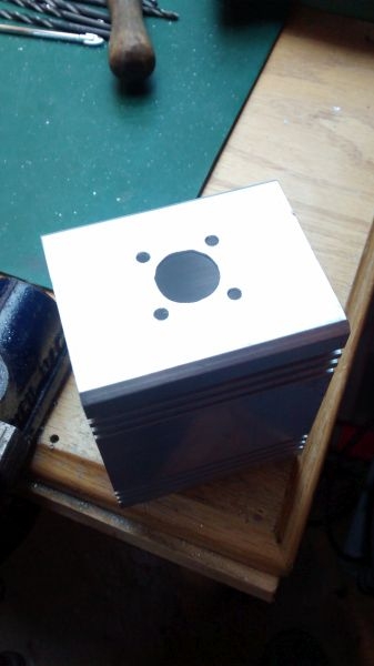
Made a start on the case for the dummy load, here is what I have selected. Its a short length of extruded aluminium box section. You can see that it has two flat plates for the front and back. These are secured by small self tapping screws. The SO239 chassis socket is the first thing to be fitted.
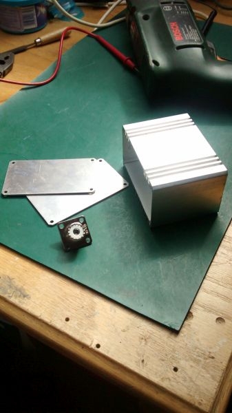
The inside of the case (top and bottom) has one perfectly flat surface and the other is stepped in the centre. I have decided to mount the socket centrally in the side of the case as this will allow maximum spare space within. This will afford more scope for additional heat sinking to be added if it is required.
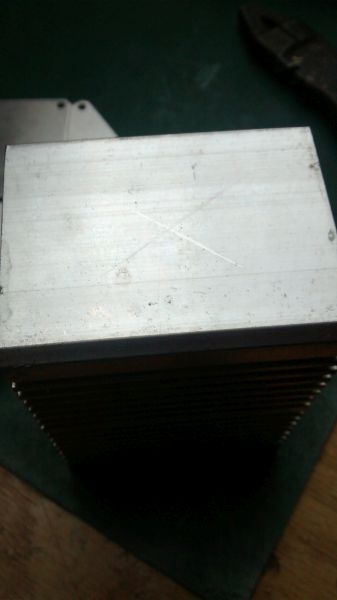
Case marked ready for drilling.
The inside of the case (top and bottom) has one perfectly flat surface and the other is stepped in the centre. I have decided to mount the socket centrally in the side of the case as this will allow maximum spare space within. This will afford more scope for additional heat sinking to be added if it is required.
Case marked ready for drilling.
Ian
-
Stanley
- Global Moderator
- Posts: 90301
- Joined: 23 Jan 2012, 12:01
- Location: Barnoldswick. Nearer to Heaven than Gloria.
Re: Amateur Radio Homebrew (Shack Culture)
No problem Ian. I have some lumps of heavy aluminium that will almost certainly do. Let me know the size you want and I can check.
Stanley Challenger Graham
Stanley's View
scg1936 at talktalk.net
"Beware of certitude" (Jimmy Reid)
The floggings will continue until morale improves!
Stanley's View
scg1936 at talktalk.net
"Beware of certitude" (Jimmy Reid)
The floggings will continue until morale improves!
-
PanBiker
- Site Administrator
- Posts: 16447
- Joined: 23 Jan 2012, 13:07
- Location: Barnoldswick - In the West Riding of Yorkshire, always was, always will be.
Re: Amateur Radio Homebrew (Shack Culture)
I will have to have a careful measure up with the inside dimensions of the case. Not sure of the overall size of the resistor pack yet so can't determine how much room will be left. If push comes to shove I will deliver it up, (socially distanced of course) with a fag packet drawing.
Ian
-
Stanley
- Global Moderator
- Posts: 90301
- Joined: 23 Jan 2012, 12:01
- Location: Barnoldswick. Nearer to Heaven than Gloria.
Re: Amateur Radio Homebrew (Shack Culture)
No problem, we will take it from there.
Stanley Challenger Graham
Stanley's View
scg1936 at talktalk.net
"Beware of certitude" (Jimmy Reid)
The floggings will continue until morale improves!
Stanley's View
scg1936 at talktalk.net
"Beware of certitude" (Jimmy Reid)
The floggings will continue until morale improves!
-
PanBiker
- Site Administrator
- Posts: 16447
- Joined: 23 Jan 2012, 13:07
- Location: Barnoldswick - In the West Riding of Yorkshire, always was, always will be.
Re: Amateur Radio Homebrew (Shack Culture)
Furthered this project a bit more last night:
I drilled the hole for the SO239, it needs 15mm but the chuck on my drill will only do 10mm, 9mm is the largest I have so 9mm it was. I enlarged the hole to 15mm with a round file. Offered up the socket and centre punched for the four fixings. I drilled one first shoved a temporary fixing in then marked the other three for drilling. Ready for the socket:
I had a choice of 6BA flange head screws with Nylock nuts or pop rivets. I offered both up, the 6BA screws are 1" long so would need cutting down.
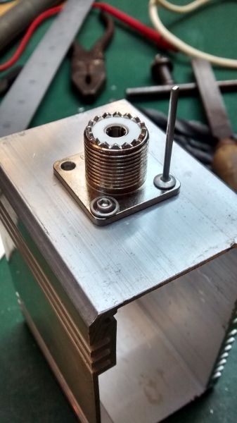
I decided to use pop rivets as they are slightly lower profile and would probably provide a better electrical contact as they expand in the fixing holes as well as pull the components together.
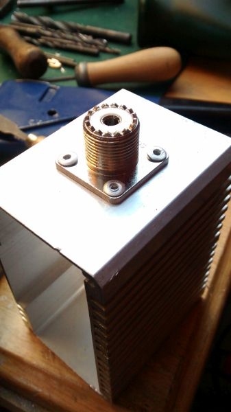
Here's the inside view of the case with socket fitted.
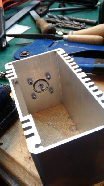
I got my steel ruler out and measured the dimensions of the internal cavity. Its 63mm wide by 38mm high, in old money that is 2.5" x 1.5", I thought the metric numbers looked familiar. The length available inside still needs to be determined and my ruler measurements may not be absolute compared to Stanley's measuring gauges for an interference fit.
I drilled the hole for the SO239, it needs 15mm but the chuck on my drill will only do 10mm, 9mm is the largest I have so 9mm it was. I enlarged the hole to 15mm with a round file. Offered up the socket and centre punched for the four fixings. I drilled one first shoved a temporary fixing in then marked the other three for drilling. Ready for the socket:
I had a choice of 6BA flange head screws with Nylock nuts or pop rivets. I offered both up, the 6BA screws are 1" long so would need cutting down.
I decided to use pop rivets as they are slightly lower profile and would probably provide a better electrical contact as they expand in the fixing holes as well as pull the components together.
Here's the inside view of the case with socket fitted.
I got my steel ruler out and measured the dimensions of the internal cavity. Its 63mm wide by 38mm high, in old money that is 2.5" x 1.5", I thought the metric numbers looked familiar. The length available inside still needs to be determined and my ruler measurements may not be absolute compared to Stanley's measuring gauges for an interference fit.
Ian
-
Stanley
- Global Moderator
- Posts: 90301
- Joined: 23 Jan 2012, 12:01
- Location: Barnoldswick. Nearer to Heaven than Gloria.
Re: Amateur Radio Homebrew (Shack Culture)
I can do that in aluminium in any thickness up to 1" Ian. I have the stock.
Stanley Challenger Graham
Stanley's View
scg1936 at talktalk.net
"Beware of certitude" (Jimmy Reid)
The floggings will continue until morale improves!
Stanley's View
scg1936 at talktalk.net
"Beware of certitude" (Jimmy Reid)
The floggings will continue until morale improves!
-
PanBiker
- Site Administrator
- Posts: 16447
- Joined: 23 Jan 2012, 13:07
- Location: Barnoldswick - In the West Riding of Yorkshire, always was, always will be.
Re: Amateur Radio Homebrew (Shack Culture)
Well, I waited and waited for the 50ohm 150w resistor to turn up but it didn't. This despite it being marked as despatched via Royal Mail complete with tracking number. It was coming from London and had a 5-7 days delivery window on it. That passed and when I tried the tracking number it was not recognised by Royal Mail! So, I contacted Ebay, they said to wait another week to see if it turned up, it didn't so I contacted the supplier. Next day I had an email to say that they had refunded me the full cost of the item.
I have changed tack slightly and modified my plan. A 250W version of the resistor is only about 50p more so I have ordered one from a different supplier. The thinking is that a 250W should run cooler than the 150W with the amount of power I will be shoving into it, more overkill, must be a good idea. Its on the same centres for mounting, the only difference is the thickness of the mounting plate. Same deal, free delivery, expected next week sometime.
I have changed tack slightly and modified my plan. A 250W version of the resistor is only about 50p more so I have ordered one from a different supplier. The thinking is that a 250W should run cooler than the 150W with the amount of power I will be shoving into it, more overkill, must be a good idea. Its on the same centres for mounting, the only difference is the thickness of the mounting plate. Same deal, free delivery, expected next week sometime.
Ian
-
Stanley
- Global Moderator
- Posts: 90301
- Joined: 23 Jan 2012, 12:01
- Location: Barnoldswick. Nearer to Heaven than Gloria.
Re: Amateur Radio Homebrew (Shack Culture)
Good luck with that. I am still a source of you need a heat sink making.
Stanley Challenger Graham
Stanley's View
scg1936 at talktalk.net
"Beware of certitude" (Jimmy Reid)
The floggings will continue until morale improves!
Stanley's View
scg1936 at talktalk.net
"Beware of certitude" (Jimmy Reid)
The floggings will continue until morale improves!

Re: Amateur Radio Homebrew (Shack Culture)
From he who knows nothing just asking, is the heat sink to be fan cooled? There could still be quite a bit of residual heat hanging about if its totally enclosed in a box.
-
PanBiker
- Site Administrator
- Posts: 16447
- Joined: 23 Jan 2012, 13:07
- Location: Barnoldswick - In the West Riding of Yorkshire, always was, always will be.
Re: Amateur Radio Homebrew (Shack Culture)
No fan in my design P. The resistor will be overrated to a degree of 10 times overkill for the initial usage to aid my 25W amplifier repair. Futuristically I could see it used momentarily in a maximum 2.5 times overkill situation and any power levels in-between. Fans are generally used in the higher load units for linear amplifier tests and the like but you are looking upwards of 400 - 1KW and above of radiated power to dump.
Ian