Rolls Royce Amateur Radio Club
-
Stanley

- Global Moderator

- Posts: 90301
- Joined: 23 Jan 2012, 12:01
- Location: Barnoldswick. Nearer to Heaven than Gloria.
Re: Rolls Royce Amateur Radio Club
Stanley Challenger Graham
Stanley's View
scg1936 at talktalk.net
"Beware of certitude" (Jimmy Reid)
The floggings will continue until morale improves!
Stanley's View
scg1936 at talktalk.net
"Beware of certitude" (Jimmy Reid)
The floggings will continue until morale improves!
-
PanBiker

- Site Administrator

- Posts: 16449
- Joined: 23 Jan 2012, 13:07
- Location: Barnoldswick - In the West Riding of Yorkshire, always was, always will be.
Re: Rolls Royce Amateur Radio Club
We leave the antenna installations for now and go back to the Morse classes which continued throughout the darker evening sessions of the Winter of 1980/81. Joe and John had done a good job and by February or March a couple of the cohort were judged to be ready to go for their Post Office Morse Tests. Dave Burrows from Nelson was one, he was a fire alarm field engineer and worked for Protec who were based on Lomeshay. The tests were administered by the Post Office and you could take it at a few main Post Offices around the country, Or at a number of Coast Guard Stations, or at a Ships Radio Inspectors office. Here is the application form that you had to fill in, The available venues that you could choose are shown in the appendix:
This is a pre decimal form with 10s as the fee, to be attached as a stamp. I think it had been modified to Postal Order after we went decimal. I know it wasn't a lot of money, probably a nominal £1 or something.
The first one to go chose Liverpool and came back with a fail, we heard of someone else who also went there and failed, the examiner was judged to be quite strict and took no prisoners. Both these lads went to alternative test centres later and passed. That put a black mark on Liverpool and just about all later candidates chose other venues. Dave was next and he went up to Cullercoates Coast Guard Station which is shown in the list as Whitley Bay Radio Station, he tipped up at the meeting following his test with a suitable grin, we had our first success. Dave sent off his pass slip and was issued with his class A licence with a station callsign G4KTR.
To my surprise in late March I was judged as ready to put in for mine. I chose a trip down the M62 to Hull to Princess Dock in Trinity House Yard. I chose a few dates in late April and early May. I have related the story in the Morse thread on the site but needless to say I passed with the comment from the pro of a "tight fist" and a compliment for correct timing and spacing. I took Eric along for moral support and the jolly down the motorway and back. The licences were administered by The Home Office at that time and they were very efficient with a prompt turnaround. Mine was almost by return of post because my Amateur Radio Certificate ( as the Class A licence required) is dated 6th May 1981. I was issued with the station call I still use, G4LWG. It's just over 40 years ago now that I qualified for my full licence.
dah dah dit, dit dit dit dit dah, dit dah dit dit, dit dah dah, dah dah dit. G4LWG
dah dit dah - (K) - invitation to transmit.
This is a pre decimal form with 10s as the fee, to be attached as a stamp. I think it had been modified to Postal Order after we went decimal. I know it wasn't a lot of money, probably a nominal £1 or something.
The first one to go chose Liverpool and came back with a fail, we heard of someone else who also went there and failed, the examiner was judged to be quite strict and took no prisoners. Both these lads went to alternative test centres later and passed. That put a black mark on Liverpool and just about all later candidates chose other venues. Dave was next and he went up to Cullercoates Coast Guard Station which is shown in the list as Whitley Bay Radio Station, he tipped up at the meeting following his test with a suitable grin, we had our first success.
To my surprise in late March I was judged as ready to put in for mine. I chose a trip down the M62 to Hull to Princess Dock in Trinity House Yard. I chose a few dates in late April and early May. I have related the story in the Morse thread on the site but needless to say I passed with the comment from the pro of a "tight fist" and a compliment for correct timing and spacing. I took Eric along for moral support and the jolly down the motorway and back. The licences were administered by The Home Office at that time and they were very efficient with a prompt turnaround. Mine was almost by return of post because my Amateur Radio Certificate ( as the Class A licence required) is dated 6th May 1981. I was issued with the station call I still use, G4LWG. It's just over 40 years ago now that I qualified for my full licence.
dah dah dit, dit dit dit dit dah, dit dah dit dit, dit dah dah, dah dah dit. G4LWG
dah dit dah - (K) - invitation to transmit.
You do not have the required permissions to view the files attached to this post.
Ian
-
Stanley
- Global Moderator
- Posts: 90301
- Joined: 23 Jan 2012, 12:01
- Location: Barnoldswick. Nearer to Heaven than Gloria.
Re: Rolls Royce Amateur Radio Club
I can't think of anywhere else where you could get that sort of inside information. (Note to self... avoid Liverpool examiners!)
Stanley Challenger Graham
Stanley's View
scg1936 at talktalk.net
"Beware of certitude" (Jimmy Reid)
The floggings will continue until morale improves!
Stanley's View
scg1936 at talktalk.net
"Beware of certitude" (Jimmy Reid)
The floggings will continue until morale improves!
-
PanBiker
- Site Administrator
- Posts: 16449
- Joined: 23 Jan 2012, 13:07
- Location: Barnoldswick - In the West Riding of Yorkshire, always was, always will be.
Re: Rolls Royce Amateur Radio Club
I think the difference was that the Post Office examiners saw it as a bit of an inconvenience and a chore whereas the uniformed Ships Radio Inspector and the lads at the Coast Guard Stations enjoyed their jobs and seemed pleased that you were keeping the mode alive.
Ian
-
PanBiker
- Site Administrator
- Posts: 16449
- Joined: 23 Jan 2012, 13:07
- Location: Barnoldswick - In the West Riding of Yorkshire, always was, always will be.
Re: Rolls Royce Amateur Radio Club
The more I think about it the more I cant remember where we got our funding from, especially in the early days. We did get a start up grant from the Welfare fund at Rolls and that was enough to get the club up and running. But ongoing costs and equipment and antenna purchases were not cheap. We did have collections then a membership fee and the odd raffle but they in themselves would not really cover the capital cost of the kit that we accumulated.
Original members that were there during the formation years are getting a bit thin on the ground. Dave Wood is still about but rarely joins our local nets. Geoff Peel (G6MZX) also but again difficult to catch. I will try Ray (G6HMN) over at Winewall he is a regular and will probably answer if I call him as he monitors the bands all day, he is essentially almost housebound due to a diving accident that he had a number of years ago. Dave would be the best as he was Chairperson. I think Ray contacts him so I will put the word out for info.
Monitoring LightningMaps at the moment, current storms are down just south of Manchester and odd ones at Fleetwood. I'll keep my antennas disconnected for the moment.
Ian
-
PanBiker
- Site Administrator
- Posts: 16449
- Joined: 23 Jan 2012, 13:07
- Location: Barnoldswick - In the West Riding of Yorkshire, always was, always will be.
Re: Rolls Royce Amateur Radio Club
I have emailed Ray but have not received a reply yet so the jury is still out on the funding aspect of the club. Needless to say we didn't rob a bank or anything dodgy like that, all our kit was legitimately obtained or purchased.
So, onto antenna deployment. The long wire antenna allowed multi-band operation with the use of an antenna tuner unit, (ATU) to match the impedance required by the transceiver. It was only useful for the some of the HF bands though so we needed some antennas for the VHF bands which were a lot busier back in the 1980's both for fixed stations and mobile operating. Just about everyone had kit for 2m or 70cm operation. From a mobile point of view this gave access to the network of repeaters around the country. 2m SSB operation was very popular for longer distance contacts and some of the more exotic modes such as auroral propagation or satellite communication. For SSB these modes required a horizontally polarized directional beam antenna. FM transmissions are conventionally made using vertical polarisation.
There were two ways to achieve this on the tower, we could have utilised a crossed YAGI antenna which can be both horizontally or vertically polarised, they have two sets of elements set 90 degrees apart this would give directional coverage for both modes. With a phasing harness you could also achieve circular polarisation which would be useful for satellite communication. The problem with that from an efficiency point of view is that it is a compromise antenna and does not give the same forward gain a single plane designs.
FM transmissions from mobile stations use omnidirectional antennas and it is accepted practice that FM signals are vertically polarised so it makes sense to use a vertical omnidirectional antenna rather than a directional beam for FM transmissions. On the other side of the coin you can get more power gain from a horizontal only beam antenna than you can from the crossed polarised equivalent.
For best overall performance it was decided we would deploy a horizontally polarised YAGI beam antenna for 2m SSB and a dual band vertical omnidirectional antenna for 2m and 70cm FM use. The 20ft rotatable 2" pole used as the top section antenna mount of the tower gave us 15ft of mast above the top bearing of the lattice tower.
When mounting antennas for different frequencies on the same pole you have to provide sufficient spacing between them to avoid cross band interference between arrays. Antennas using the same frequencies but different polarisations can be mounted closer together. We intended to mount an HF beam on the tower as well, this would be the largest of the arrays and would sit at the bottom of the mast just above the bearing platform.
Ideally for the 2m beam we needed at least a wavelength of spacing below the array , so for a 2m antenna that is roughly 12.5ft above where the lower frequency HF array would be so 1.5ft from the top of the mast. 42.5ft from the ground. This would leave 18", which is roughly a quarter wavelength at 144Mhz above the beam for mounting a vertical antenna on the top of the mast.
We chose a Cushcraft 14 element Junior Boomer YAGI for 2m SSB use. This design gave us about 15dBi forward gain, the antenna was around 4.2m long which in old money is just short of 14ft long, the elements on the array were all around a half wavelength long so roughly 1m each. The antenna used a gamma match on the driven element for resonance adjustments. Clearly you cant make the matching adjustments once it is mounted on the tower. The gamma match is 40 odd foot up and 6ft along the beam! You have to do these adjustments at a more convenient level so we rigged a shorter 20ft guyed mast up on the sports field to set the antenna up before deployment. We chose a nice fine Sunday for the deployment and split into two teams. Bill and myself and a couple of others were the tower deployment team. John York and a few others rigged the temporary mast and used a portable multi-mode 2m transceiver to drive the antenna and optimise the matching for the centre of the SSB portion of the 2m band. We had built the antenna the previous week in the shack and made up the coax feeder cable ready for deployment.
The problem now was how to safely get almost to the top of a 15ft 2" diameter pole mounted 30ft above the ground. I have mentioned that the tower was a tapered lattice design and we had only been able to use the first two 15ft sections. We used two short lengths of scaffold pole which we clamped horizontally through the tower just below the bearing platform. This gave us two protruding horizontal poles at each side. What we did was to split an 18ft aluminium extension ladder, sit and clamp the bottom rung on the horizontal poles and then lash each section to the top of the tower at either side of the pole with cross lashings between the two sections. Effectively temporarily extending the tower. It gave us sufficient supported height to fix the antenna to the mast to captivate it and then lift it to the correct height before tightening off the brackets. The BT safety harnesses came in very handy for this job, we had a ladder each at either side of the mast and it meant we could work with both hands free. Bill was a bit lankier than me so his reach came in handy for the final fixing and orientation of the array. We have better take off to the North from Barlick for VHF so we organised the rotator stop at South so the rotator had full travel through East, North and West.
The ladder arrangement was fine for the 2m beam antenna as it was a horizontal mount. The ladders though came a good 6ft short of the top of the mast which meant that we couldn't use the same method for mounting a vertical on the top. We would be at absolutely full stretch which is not a good idea at height with unwieldy unsecured equipment, particularly as a dual band vertical for 2m and 70cm is a good 6ft - 8ft long and the fixings are only at the bottom end! We had a cunning plan though for that deployment.
Another fine Tuesday evening we gave the local fire brigade a challenge and some practice drill with their extension ladder. After a brew in the shack and instruction on what we required. We gave them the right sized spanners and some cable ties for dressing the feeder down the pole to the top of the tower. The antenna had the cable already attached at the business end and it was sorted within about 15 minutes. A change for the lads from their normal drill up the hose tower in the fire station yard on a Tuesday night.
Next challenge was a tri-band HF beam but that was a totally different kettle of fish as they are quite a lump both in size and weight and that deployment is for a later post.
So, onto antenna deployment. The long wire antenna allowed multi-band operation with the use of an antenna tuner unit, (ATU) to match the impedance required by the transceiver. It was only useful for the some of the HF bands though so we needed some antennas for the VHF bands which were a lot busier back in the 1980's both for fixed stations and mobile operating. Just about everyone had kit for 2m or 70cm operation. From a mobile point of view this gave access to the network of repeaters around the country. 2m SSB operation was very popular for longer distance contacts and some of the more exotic modes such as auroral propagation or satellite communication. For SSB these modes required a horizontally polarized directional beam antenna. FM transmissions are conventionally made using vertical polarisation.
There were two ways to achieve this on the tower, we could have utilised a crossed YAGI antenna which can be both horizontally or vertically polarised, they have two sets of elements set 90 degrees apart this would give directional coverage for both modes. With a phasing harness you could also achieve circular polarisation which would be useful for satellite communication. The problem with that from an efficiency point of view is that it is a compromise antenna and does not give the same forward gain a single plane designs.
FM transmissions from mobile stations use omnidirectional antennas and it is accepted practice that FM signals are vertically polarised so it makes sense to use a vertical omnidirectional antenna rather than a directional beam for FM transmissions. On the other side of the coin you can get more power gain from a horizontal only beam antenna than you can from the crossed polarised equivalent.
For best overall performance it was decided we would deploy a horizontally polarised YAGI beam antenna for 2m SSB and a dual band vertical omnidirectional antenna for 2m and 70cm FM use. The 20ft rotatable 2" pole used as the top section antenna mount of the tower gave us 15ft of mast above the top bearing of the lattice tower.
When mounting antennas for different frequencies on the same pole you have to provide sufficient spacing between them to avoid cross band interference between arrays. Antennas using the same frequencies but different polarisations can be mounted closer together. We intended to mount an HF beam on the tower as well, this would be the largest of the arrays and would sit at the bottom of the mast just above the bearing platform.
Ideally for the 2m beam we needed at least a wavelength of spacing below the array , so for a 2m antenna that is roughly 12.5ft above where the lower frequency HF array would be so 1.5ft from the top of the mast. 42.5ft from the ground. This would leave 18", which is roughly a quarter wavelength at 144Mhz above the beam for mounting a vertical antenna on the top of the mast.
We chose a Cushcraft 14 element Junior Boomer YAGI for 2m SSB use. This design gave us about 15dBi forward gain, the antenna was around 4.2m long which in old money is just short of 14ft long, the elements on the array were all around a half wavelength long so roughly 1m each. The antenna used a gamma match on the driven element for resonance adjustments. Clearly you cant make the matching adjustments once it is mounted on the tower. The gamma match is 40 odd foot up and 6ft along the beam! You have to do these adjustments at a more convenient level so we rigged a shorter 20ft guyed mast up on the sports field to set the antenna up before deployment. We chose a nice fine Sunday for the deployment and split into two teams. Bill and myself and a couple of others were the tower deployment team. John York and a few others rigged the temporary mast and used a portable multi-mode 2m transceiver to drive the antenna and optimise the matching for the centre of the SSB portion of the 2m band. We had built the antenna the previous week in the shack and made up the coax feeder cable ready for deployment.
The problem now was how to safely get almost to the top of a 15ft 2" diameter pole mounted 30ft above the ground. I have mentioned that the tower was a tapered lattice design and we had only been able to use the first two 15ft sections. We used two short lengths of scaffold pole which we clamped horizontally through the tower just below the bearing platform. This gave us two protruding horizontal poles at each side. What we did was to split an 18ft aluminium extension ladder, sit and clamp the bottom rung on the horizontal poles and then lash each section to the top of the tower at either side of the pole with cross lashings between the two sections. Effectively temporarily extending the tower. It gave us sufficient supported height to fix the antenna to the mast to captivate it and then lift it to the correct height before tightening off the brackets. The BT safety harnesses came in very handy for this job, we had a ladder each at either side of the mast and it meant we could work with both hands free. Bill was a bit lankier than me so his reach came in handy for the final fixing and orientation of the array. We have better take off to the North from Barlick for VHF so we organised the rotator stop at South so the rotator had full travel through East, North and West.
The ladder arrangement was fine for the 2m beam antenna as it was a horizontal mount. The ladders though came a good 6ft short of the top of the mast which meant that we couldn't use the same method for mounting a vertical on the top. We would be at absolutely full stretch which is not a good idea at height with unwieldy unsecured equipment, particularly as a dual band vertical for 2m and 70cm is a good 6ft - 8ft long and the fixings are only at the bottom end! We had a cunning plan though for that deployment.
Another fine Tuesday evening we gave the local fire brigade a challenge and some practice drill with their extension ladder. After a brew in the shack and instruction on what we required. We gave them the right sized spanners and some cable ties for dressing the feeder down the pole to the top of the tower. The antenna had the cable already attached at the business end and it was sorted within about 15 minutes.
Next challenge was a tri-band HF beam but that was a totally different kettle of fish as they are quite a lump both in size and weight and that deployment is for a later post.
Ian
-
Stanley
- Global Moderator
- Posts: 90301
- Joined: 23 Jan 2012, 12:01
- Location: Barnoldswick. Nearer to Heaven than Gloria.
Re: Rolls Royce Amateur Radio Club
Read every word.... don't understand it but I know good reporting when I see it! 
Stanley Challenger Graham
Stanley's View
scg1936 at talktalk.net
"Beware of certitude" (Jimmy Reid)
The floggings will continue until morale improves!
Stanley's View
scg1936 at talktalk.net
"Beware of certitude" (Jimmy Reid)
The floggings will continue until morale improves!


Re: Rolls Royce Amateur Radio Club
Clever sod. Me too. 
-
PanBiker
- Site Administrator
- Posts: 16449
- Joined: 23 Jan 2012, 13:07
- Location: Barnoldswick - In the West Riding of Yorkshire, always was, always will be.
Re: Rolls Royce Amateur Radio Club
OK, without the correct jargon and in layman's terms we fastened a giant version (4.2m long and 1m wide) of a UHF TV aerial to a 2" pole 42ft off the ground. We then put a vertical stick type antenna (6 to 8ft long) on the top of the pole 45ft above the ground. I think using the local firemen and their kit should be easily understood.
No different to engine building posts with Morse tapers, Unbrako screws, eccentric straps etc, each to their own, I know that vexes me.
No different to engine building posts with Morse tapers, Unbrako screws, eccentric straps etc, each to their own, I know that vexes me.
Ian

Re: Rolls Royce Amateur Radio Club
I'm enjoying this thread. Very detailed, and I 'get' most of it. Nice to see terms like G5RV, SSB, dBi etc used again.
The use of the FIre Brigade is a sore point with me. I was once refused service by two different Brigades, and to get a response it took a threat from one of the ambulance drivers who was on scene, that the next call would be to the newsdesk of the Sun newspaper if they didn't attend my 999 call.
That worked.
Born to be mild
Sapere Aude
Ego Lego
Preferred pronouns - Thou, Thee, Thy, Thine
My non-working days are Monday - Sunday
Sapere Aude
Ego Lego
Preferred pronouns - Thou, Thee, Thy, Thine
My non-working days are Monday - Sunday
Re: Rolls Royce Amateur Radio Club
It's an interesting read, it's just some of the terminology that loses me. I get a rough idea of what's going onPanBiker wrote: ↑31 Jul 2021, 11:20 OK, without the correct jargon and in layman's terms we fastened a giant version (4.2m long and 1m wide) of a UHF TV aerial to a 2" pole 42ft off the ground. We then put a vertical stick type antenna (6 to 8ft long) on the top of the pole 45ft above the ground. I think using the local firemen and their kit should be easily understood.
No different to engine building posts with Morse tapers, Unbrako screws, eccentric straps etc, each to their own, I know that vexes me.
Kev
Stylish Fashion Icon.

Stylish Fashion Icon.

-
PanBiker
- Site Administrator
- Posts: 16449
- Joined: 23 Jan 2012, 13:07
- Location: Barnoldswick - In the West Riding of Yorkshire, always was, always will be.
Re: Rolls Royce Amateur Radio Club
Sorry to hear of your downer with the fire brigade Dave, our lads are more accommodating, not a full time brigade but all local lads and lassies.
Anyway I am glad that at least one member can understand the majority of my banter. So, onwards and upwards (literally) with the largest of the antennas for the tower. Next one to be added and the last apart from the odd wire experiment attached to the lattice from time to time. A tri-band HF Yagi beam for the top end of the HF spectrum. The array covered the 20m, 15m and 10m bands so in frequency 14MHz, 21MHz and 28MHz sections of the amateur allocation. Here is a picture of a similar array as they say a picture is worth a thousand words.
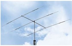
It's a three element trapped dipole design. At the HF frequencies the wavelengths get increasingly longer as you decrease the frequency so designing compact antennas gets more challenging. In this design there is one trapped dipole for each band that the antenna covers.
So, take the example of the longest element which is for the 20m band. A full wavelength is 20m long so a half wave will be 10m long and a quarter wave 5m long. That should be quite easy to understand. Quite clearly it would be rather difficult to have a single element in this design that is 20m long or even 10m. However when you get to the quarter wave at 5m you are getting into a manageable length. You can use an odd trick to effectively extend the length electrically and that is to add a coil of wire (or trap) into the design. If you look carefully at the picture you will see that there is a coil (trap) in each side of each of the element. These are there to effectively extend the electrical length of the dipole without unduly extending the physical length of the elements. This allows you to construct antennas that are more compact.
The dimensions of this design are as follows. The boom is 4.3m long. The 20m element is the longest and at the back of the array and is 8.54m long. The traps on the element will extend that to be the equivalent of a half wave so electrically 10m long. The front element is the shortest physically and is for the 10m band the traps on that one will almost certainly make it more than a single wavelength for its design frequency. The middle element is for 15m and is longer than the front 10m element but shorter than the back 20m element. These are single dipoles and as such don't have any directional capabilities if they were stand alone. The signal radiated from a straight dipole is uniform in both directions a 1:1 relationship.
The basis of a YAGI design beam antenna is quite simple If you add a director element in front and a reflector element behind the driven element you turn the almost uniform radiation pattern into a more directed beam. The reflector forces RF energy from the dipole forwards from the driven element in the middle and the director amplifies the radiated RF signal. The array then is said to have forward gain which is expressed as a dB value which equates to a power gain as you are concentrating any reflected signal, reflecting it back and adding it to the forward lobe of the radiation pattern of the antenna. Generally the more director elements you have the more forward gain you get. You don't get much with a three element beam at HF frequencies but it is a bonus over the power you apply to the antenna. It is a lot easier to add more directors to higher frequency antennas as the element lengths are all shorter so you can have much more compact arrays. The 12 element VHF array described in the last post has a claimed 15dBi forward gain where as the 3 element HF array only has 8dBi. Manufacturers tend to quote the gain figures under technically ideal and best case scenarios often theoretically based on design algorithms. 3dBi gain is 100% power gain in relation to a straight dipole. You can roughly equate that to shoving 10w of power into a 3dbi rated antenna, you will get an effective radiated power (ERP) of 20w There are many influencing factors such a height of the antennas, local obstructions, losses on cables and connectors that will effect the radiation pattern of a given antenna. Constants though are that the more elements you have in an antenna array the narrower the band width will be so you get more forward radiated power. More bangs for your buck if you like.
Here endeth the lesson.
So, a few more stats we have an antenna with a boom length of 4.3m, the longest element on the boom is 8.54m long so it projects 4.27m at each side of the boom. The other two elements are a bit shorter. This rolls into a turning radius once mounted of 4.72m it has a 60 degree beam width which means the forward lobe of the radiation pattern will be 60 degrees wide. it has 8dBi claimed gain and can handle 2kW of RF power and weighs in at 30lbs.
We assembled the antenna on the ground, actually on a number of chairs set up in the car park to prop up the boom and elements at each side. There is only one main connector on the antenna, each of the elements are linked using a coax phasing harness that runs along the boom. We have to get this up to just above the top bearing platform of the tower, it will be attached to the pole with about 6" clearance from the bearing, so 30ft above ground.
We used a couple of extension ladders to create a slide up the side of the tower. We first of all attached a clamp to the extension pole of the tower, this had a hole drilled through the side wall of the clamp that could take the hook of a small pulley suitable for polypropylene rope which we passed through the pulley this would act as both a method of hauling the antenna to height and as a safety line to stop it from falling back down. We clamped a scaffold pole across the tower just below the bearing platform, longer than the ones we had used for the laddering for the VHF array. This allowed us to secure two extension ladders to the pole at the top by their top rungs the top of the ladders extended slightly above the poles so created a temporary parking spot for the boom. to ensure a smooth pull up the ladders we took the 90 degree mounting bracket from the boom and installed that first to the pole on the tower this left a straight clean boom which would make the hauling a lot easier. Once the superstructure was set up we rotated the VHF array so it was side on to the ladders as the elements of the HF beam at 4.3m proud of the boom would have to be lifted higher than the VHF antenna until the array could be rotated to the horizontal. We couldn't take any risks with this as it was about £600 worth of kit.
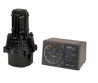
Bill and I harnessed up and clipped ourselves to the top of the lattice to await delivery. The rope was attached in two places along the beam in a Y formation so that the boom would stay horizontal on the pull even though we were only using a single rope. Four of the lads carried the array over to the ladder slide above their heads the rope team then took up the slack and started the haul steady away. A couple of the lads walked the boom high enough up the ladder so that the longest element was clear of the ground. The boom could then be put on the ladder and hauled up a few inches at a time we had two lads on the ladders who kept the elements parallel to the slide. When we got the boom to the top of the ladder Bill and I took over and lifted the boom first into the temporary parking position behind the tops of the ladders. It was now secure from falling so we could have a breather it was still in one piece. It was fairly simple then between us to lift it to the top of the bearing platform and then offer it to the pre-installed bracket on the pole. We rotated it to the horizontal and once had it secure we could orientate it so that it so that the front of the beam aligned with the VHF array above. We had an observer underneath that told us when to fasten it off when it was correctly aligned. Rotation was checked and as before with the VHF array we created a loop in the feeder coax to allow for the 360 degree rotation before dressing the cables down the side off the tower. The weight of antennas on the tower was around 50 lbs in total excluding the weight of the 20ft extension pole. I mentioned the Yamaha heavy duty rotator we had bought for the installation. I think it was actually a Yaesu medium heavy duty unit similar to this. These can handle 200Kg of vertical load.
Questions on a postcard or within this thread.
Anyway I am glad that at least one member can understand the majority of my banter. So, onwards and upwards (literally) with the largest of the antennas for the tower. Next one to be added and the last apart from the odd wire experiment attached to the lattice from time to time. A tri-band HF Yagi beam for the top end of the HF spectrum. The array covered the 20m, 15m and 10m bands so in frequency 14MHz, 21MHz and 28MHz sections of the amateur allocation. Here is a picture of a similar array as they say a picture is worth a thousand words.
It's a three element trapped dipole design. At the HF frequencies the wavelengths get increasingly longer as you decrease the frequency so designing compact antennas gets more challenging. In this design there is one trapped dipole for each band that the antenna covers.
So, take the example of the longest element which is for the 20m band. A full wavelength is 20m long so a half wave will be 10m long and a quarter wave 5m long. That should be quite easy to understand. Quite clearly it would be rather difficult to have a single element in this design that is 20m long or even 10m. However when you get to the quarter wave at 5m you are getting into a manageable length. You can use an odd trick to effectively extend the length electrically and that is to add a coil of wire (or trap) into the design. If you look carefully at the picture you will see that there is a coil (trap) in each side of each of the element. These are there to effectively extend the electrical length of the dipole without unduly extending the physical length of the elements. This allows you to construct antennas that are more compact.
The dimensions of this design are as follows. The boom is 4.3m long. The 20m element is the longest and at the back of the array and is 8.54m long. The traps on the element will extend that to be the equivalent of a half wave so electrically 10m long. The front element is the shortest physically and is for the 10m band the traps on that one will almost certainly make it more than a single wavelength for its design frequency. The middle element is for 15m and is longer than the front 10m element but shorter than the back 20m element. These are single dipoles and as such don't have any directional capabilities if they were stand alone. The signal radiated from a straight dipole is uniform in both directions a 1:1 relationship.
The basis of a YAGI design beam antenna is quite simple If you add a director element in front and a reflector element behind the driven element you turn the almost uniform radiation pattern into a more directed beam. The reflector forces RF energy from the dipole forwards from the driven element in the middle and the director amplifies the radiated RF signal. The array then is said to have forward gain which is expressed as a dB value which equates to a power gain as you are concentrating any reflected signal, reflecting it back and adding it to the forward lobe of the radiation pattern of the antenna. Generally the more director elements you have the more forward gain you get. You don't get much with a three element beam at HF frequencies but it is a bonus over the power you apply to the antenna. It is a lot easier to add more directors to higher frequency antennas as the element lengths are all shorter so you can have much more compact arrays. The 12 element VHF array described in the last post has a claimed 15dBi forward gain where as the 3 element HF array only has 8dBi. Manufacturers tend to quote the gain figures under technically ideal and best case scenarios often theoretically based on design algorithms. 3dBi gain is 100% power gain in relation to a straight dipole. You can roughly equate that to shoving 10w of power into a 3dbi rated antenna, you will get an effective radiated power (ERP) of 20w There are many influencing factors such a height of the antennas, local obstructions, losses on cables and connectors that will effect the radiation pattern of a given antenna. Constants though are that the more elements you have in an antenna array the narrower the band width will be so you get more forward radiated power. More bangs for your buck if you like.
Here endeth the lesson.
So, a few more stats we have an antenna with a boom length of 4.3m, the longest element on the boom is 8.54m long so it projects 4.27m at each side of the boom. The other two elements are a bit shorter. This rolls into a turning radius once mounted of 4.72m it has a 60 degree beam width which means the forward lobe of the radiation pattern will be 60 degrees wide. it has 8dBi claimed gain and can handle 2kW of RF power and weighs in at 30lbs.
We assembled the antenna on the ground, actually on a number of chairs set up in the car park to prop up the boom and elements at each side. There is only one main connector on the antenna, each of the elements are linked using a coax phasing harness that runs along the boom. We have to get this up to just above the top bearing platform of the tower, it will be attached to the pole with about 6" clearance from the bearing, so 30ft above ground.
We used a couple of extension ladders to create a slide up the side of the tower. We first of all attached a clamp to the extension pole of the tower, this had a hole drilled through the side wall of the clamp that could take the hook of a small pulley suitable for polypropylene rope which we passed through the pulley this would act as both a method of hauling the antenna to height and as a safety line to stop it from falling back down. We clamped a scaffold pole across the tower just below the bearing platform, longer than the ones we had used for the laddering for the VHF array. This allowed us to secure two extension ladders to the pole at the top by their top rungs the top of the ladders extended slightly above the poles so created a temporary parking spot for the boom. to ensure a smooth pull up the ladders we took the 90 degree mounting bracket from the boom and installed that first to the pole on the tower this left a straight clean boom which would make the hauling a lot easier. Once the superstructure was set up we rotated the VHF array so it was side on to the ladders as the elements of the HF beam at 4.3m proud of the boom would have to be lifted higher than the VHF antenna until the array could be rotated to the horizontal. We couldn't take any risks with this as it was about £600 worth of kit.
Bill and I harnessed up and clipped ourselves to the top of the lattice to await delivery. The rope was attached in two places along the beam in a Y formation so that the boom would stay horizontal on the pull even though we were only using a single rope. Four of the lads carried the array over to the ladder slide above their heads the rope team then took up the slack and started the haul steady away. A couple of the lads walked the boom high enough up the ladder so that the longest element was clear of the ground. The boom could then be put on the ladder and hauled up a few inches at a time we had two lads on the ladders who kept the elements parallel to the slide. When we got the boom to the top of the ladder Bill and I took over and lifted the boom first into the temporary parking position behind the tops of the ladders. It was now secure from falling so we could have a breather it was still in one piece.
Questions on a postcard or within this thread.
Ian
Re: Rolls Royce Amateur Radio Club
Ian - It's a terrible shame that you were never the local R.I.S officer. You'd have been ideal. The problem is that the adverts were usually in the Daily Mail, so you'd be very unlikely to see them.
Born to be mild
Sapere Aude
Ego Lego
Preferred pronouns - Thou, Thee, Thy, Thine
My non-working days are Monday - Sunday
Sapere Aude
Ego Lego
Preferred pronouns - Thou, Thee, Thy, Thine
My non-working days are Monday - Sunday
-
PanBiker
- Site Administrator
- Posts: 16449
- Joined: 23 Jan 2012, 13:07
- Location: Barnoldswick - In the West Riding of Yorkshire, always was, always will be.
Re: Rolls Royce Amateur Radio Club
For every problem there is a solution. We liked to operate as safely as possible in all circumstances.
Ian
-
Whyperion

- Senior Member
- Posts: 3073
- Joined: 23 Jan 2012, 22:13
- Location: Stockport, after some time in Burnley , After leaving Barnoldswick , except when I am in London
Re: Rolls Royce Amateur Radio Club
For anyone considering putting up an antenna array today, if the Fire Brigade are a bit tied up, a nice request to the Royal Engineers Territorials evening practice should be tried.
Somewhere I have a photo of my Dad's unit in Egypt running up temporary comms during national service mopping up in the middle east after WW2.
Somewhere I have a photo of my Dad's unit in Egypt running up temporary comms during national service mopping up in the middle east after WW2.
-
Stanley
- Global Moderator
- Posts: 90301
- Joined: 23 Jan 2012, 12:01
- Location: Barnoldswick. Nearer to Heaven than Gloria.
Re: Rolls Royce Amateur Radio Club
Anointer good episode Ian.....
Stanley Challenger Graham
Stanley's View
scg1936 at talktalk.net
"Beware of certitude" (Jimmy Reid)
The floggings will continue until morale improves!
Stanley's View
scg1936 at talktalk.net
"Beware of certitude" (Jimmy Reid)
The floggings will continue until morale improves!
-
PanBiker
- Site Administrator
- Posts: 16449
- Joined: 23 Jan 2012, 13:07
- Location: Barnoldswick - In the West Riding of Yorkshire, always was, always will be.
Re: Rolls Royce Amateur Radio Club
Thanks Stanley.
On another matter, I haven't had a reply yet from Ray, I hope he's alright. I will try giving him a shout again on 2m.
I think I would just ask an aerial rigger or a younger local radio amateur if I was contemplating any mast based stuff on our house that I couldn't manage.
On another matter, I haven't had a reply yet from Ray, I hope he's alright. I will try giving him a shout again on 2m.
Ian
Re: Rolls Royce Amateur Radio Club
I'm keeping up, some of the terminology is starting to make sense.
Kev
Stylish Fashion Icon.
Stylish Fashion Icon.
-
PanBiker
- Site Administrator
- Posts: 16449
- Joined: 23 Jan 2012, 13:07
- Location: Barnoldswick - In the West Riding of Yorkshire, always was, always will be.
Re: Rolls Royce Amateur Radio Club
That's good Kev, ask for any clarification you might need.
I didn't manage to contact Ray but I know he is OK. I had a QSO with Kevin in Gargrave this afternoon and he was talking to Ray this morning. I have just missed him.
I didn't manage to contact Ray but I know he is OK. I had a QSO with Kevin in Gargrave this afternoon and he was talking to Ray this morning. I have just missed him.
Ian
-
Stanley
- Global Moderator
- Posts: 90301
- Joined: 23 Jan 2012, 12:01
- Location: Barnoldswick. Nearer to Heaven than Gloria.
Re: Rolls Royce Amateur Radio Club
That's good!
Stanley Challenger Graham
Stanley's View
scg1936 at talktalk.net
"Beware of certitude" (Jimmy Reid)
The floggings will continue until morale improves!
Stanley's View
scg1936 at talktalk.net
"Beware of certitude" (Jimmy Reid)
The floggings will continue until morale improves!
-
PanBiker
- Site Administrator
- Posts: 16449
- Joined: 23 Jan 2012, 13:07
- Location: Barnoldswick - In the West Riding of Yorkshire, always was, always will be.
Re: Rolls Royce Amateur Radio Club
I think I have Geoff Peels email address somewhere, it's not in my Outlook address book but I think I have it on a card and I will cross check it against the one on his QRZ (Online Amateur Radio Directory) page. Geoff is another founding member and worked at Rolls so I'll ask him the same about the funding aspect.
Ian
-
PanBiker
- Site Administrator
- Posts: 16449
- Joined: 23 Jan 2012, 13:07
- Location: Barnoldswick - In the West Riding of Yorkshire, always was, always will be.
Re: Rolls Royce Amateur Radio Club
I got a reply from Geoff and then had a chat on the phone. I got it wrong about the membership subscription, we didn't have one. The main capital funding came from the Rolls Royce Sports and Social Club which had quite a few sections. I knew we got initial funding from them when the club started up but I had forgotten that sections had to put a bid in each year which is what Les and David did each year. We did have raffles etc which made a few quid and other events that would raise a small surplus but the main funding was annually from the Sports and Social Club. Glad that one is sorted.
Ian
-
PanBiker
- Site Administrator
- Posts: 16449
- Joined: 23 Jan 2012, 13:07
- Location: Barnoldswick - In the West Riding of Yorkshire, always was, always will be.
Re: Rolls Royce Amateur Radio Club
The funding allowed us to buy the transceivers for club use. Geoff remembers a Yausu FT 767 and so do I. That was one one of the first "shack in a box transceivers" It was supplied as a multi mode HF transceiver covering 1.8MHz (160m) to 30MHz top end of the 10m band with a general coverage receiver. The transceiver could be fitted with expansion modules for 50Mhz (6m), 144MHz (2m) and 433MHz (70cm) bands. I remember Geoff and myself fitting those.
RigPix Database - FT-767GX
This wasn't produced until 1986. I am fairly sure that we had two separate transceivers before that. One for the HF bands and another for the VHF bands which covered just 2m and 70cm. I cant remember what they were though. Of course members could bring their own kit if they wanted to use the antenna system at the shack.
We had a couple of annual events at the club. During the summer we had a Fox Hunt night. No animals were hurt in this activity as it was a DF (direction finding) competition. Each years winners acted as the fox for the next years competition which was run on the 2m band. The fox station would hide in an undisclosed location of their choice which had to be within a 3 mile radius and transmit for sixty seconds about every five minutes. Once the first transmission was made the fox station could not move location. The rules also stipulated that the fox had to be in a reasonably accessible position, so not sat behind a wall halfway up Weets. It was up to the hunting teams to locate the fox, first one to do so won the trophy.
This encouraged the construction of small portable directional antennas that you could use to get a bearing on the transmissions. A popular choice was a 2 element design developed by Swiss Radio Amateur HB9CV
2m HB9CV antenna
Seeker teams then would move around the area between transmissions and take further bearings in an effort to get a cross location to find the fox. The competition generally lasted a couple of hours. If the seekers were struggling the fox may give cryptic clues as to their location so as to move things along. Once found it was back to the Social Club for the trophy presentation a beer and to exchange tales of the hunt.
After presentation the trophy was handed back at the end of the night for engraving.
Here is the trophy my mate Bill Roberts (G4PWC) and I won in 1989.
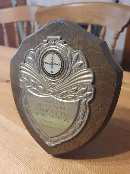
Another club member competition in the next episode....
RigPix Database - FT-767GX
This wasn't produced until 1986. I am fairly sure that we had two separate transceivers before that. One for the HF bands and another for the VHF bands which covered just 2m and 70cm. I cant remember what they were though. Of course members could bring their own kit if they wanted to use the antenna system at the shack.
We had a couple of annual events at the club. During the summer we had a Fox Hunt night. No animals were hurt in this activity as it was a DF (direction finding) competition. Each years winners acted as the fox for the next years competition which was run on the 2m band. The fox station would hide in an undisclosed location of their choice which had to be within a 3 mile radius and transmit for sixty seconds about every five minutes. Once the first transmission was made the fox station could not move location. The rules also stipulated that the fox had to be in a reasonably accessible position, so not sat behind a wall halfway up Weets. It was up to the hunting teams to locate the fox, first one to do so won the trophy.
This encouraged the construction of small portable directional antennas that you could use to get a bearing on the transmissions. A popular choice was a 2 element design developed by Swiss Radio Amateur HB9CV
2m HB9CV antenna
Seeker teams then would move around the area between transmissions and take further bearings in an effort to get a cross location to find the fox. The competition generally lasted a couple of hours. If the seekers were struggling the fox may give cryptic clues as to their location so as to move things along. Once found it was back to the Social Club for the trophy presentation a beer and to exchange tales of the hunt.
After presentation the trophy was handed back at the end of the night for engraving.
Here is the trophy my mate Bill Roberts (G4PWC) and I won in 1989.
Another club member competition in the next episode....
Ian
-
PanBiker
- Site Administrator
- Posts: 16449
- Joined: 23 Jan 2012, 13:07
- Location: Barnoldswick - In the West Riding of Yorkshire, always was, always will be.
Re: Rolls Royce Amateur Radio Club
Change of tack on the next episode. I have been rummaging in the cockloft and came across my QSL cards from 40 years ago including examples of the Club cards that we sent out. We discussed QSL cards in another thread a few years ago when Tiz came across one from a German Short Wave Listener. As a refresher of their purpose, the Q code "QSL" when sent in Morse means "please confirm contact" so a QSL card is just that. The equivalent of a postcard to confirm radio contact. It was conventional before the advent of the internet to send a physical card and you still can if you wish. National radio societies maintain volunteer operatives who run QSL bureaus for clearing cards and sending on to the recipients. If you use the service you lodged a batch of pre paid self addresses envelopes with your regional QSL rep, you sent batches of your own cards out via the same route. Many amateurs will use cards some of which may become collectable within the fraternity. Many QSL cards are now exchanged as E-cards and done via the internet via the QRZ database etc.
When we originally started the club station up we just used generic designed cards which were readily available and just overprinted with your station . call sign and simple graphics The confirmation information from your log was entered on the back of these.
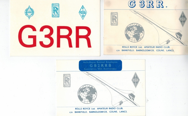
The top two were used in the early days of the club although the one on the right was the first used from 1980 onwards. The coloured one on the left was slightly later maybe 1983 or thereabouts. The one at the bottom was for a special event station that we ran to celebrate 25 years of the Rolls Royce Retired Employees Association. You can tell it was special event station by the GB prefix of the call sign. You can tell that the Concord design was the first one as it's address is just shown as c/o the Bankfield factory. It's also a standard club card that has been modified with a simple adhesive sticker to change the card. This avoided buying a complete batch of cards and ending up with many that would not get used. I think 200 or so was the minimum that you could order and of course they got cheaper if you increased the quantity. I think I originally got 200 when I passed my RAE and held GG8UKC and then 500 when I got my current call sign G4LWG. I have not come across any of my current cards though.
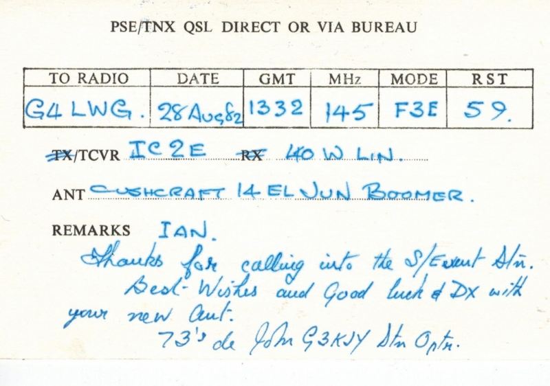
You can tell that we ran this Special Event Station on 28th August 1982. Contact was at 1332, (probably when I was having a break from operating, at home for lunch). Contact was made on 145MHz so the 2m band mode is F3E so FM modulation. Equipment at the shack was an Icom IC2E which was a hand held transeiver which I happen to know was John's own kit. He was running it into a 40w linear amplifier as the IC2E only gave 1.5w out as standard. Antenna was the 14 element Cushcraft that we deployed at the top of the tower. I can also tell from John's remarks that it was not long after I had put up my 11 element version of the antenna at my home on York Street at the time. He signs off the contact with his own call sign (G3KJY) as station operator with the standard 73's (best wishes) and good luck for DX (long distance contacts) with my new antenna. I would have reciprocated to the club with one of my cards. These would not have gone via the Bureau but hand delivered.
The next image shows our later QSL card which became a bit of a star and ensured that contact with the club station would get them a unique card.
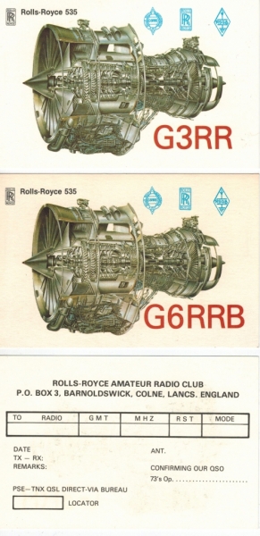
The top one is for the Class A licence call sign that we held G3RR. The two letter call was a re-issue and had been held by a previous radio amateur in the 1930's who had died so the call sign became available. At the time you could request call signs for clubs that would be representative of the club name etc.
The second card call sign was obtained for class B licensees use so that they could run the station unattended on the bands allowed at the time with that class of licence (144MHz and above). If a Class A licensee was in attendance they could operate using the G3RR call sign.
The design shows the cut out representation of the flagship turbine developed in Barlick at the time the 535. It has the RR badge, the RRARC logo which shows we hold more than one call sign and the RSGB (Radio Society of Great Britain) logo.
Third image is the generic blank back of a card.
When the club disbanded the call signs would go back into the pool when the licence expired. G3RR is now operated by Hucknall Rolls Royce Amateur Radio Club. This is the current entry on the online QRZ Amateur Radio database.
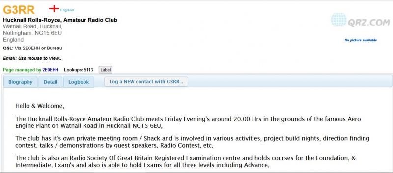
Curiously the database still shows the G6RRB call sign as being administered by the club secretary Les (G4ILG) although he died quite a few years ago. Ofcom must not have been told by the last incumbents of the club
When we originally started the club station up we just used generic designed cards which were readily available and just overprinted with your station . call sign and simple graphics The confirmation information from your log was entered on the back of these.
The top two were used in the early days of the club although the one on the right was the first used from 1980 onwards. The coloured one on the left was slightly later maybe 1983 or thereabouts. The one at the bottom was for a special event station that we ran to celebrate 25 years of the Rolls Royce Retired Employees Association. You can tell it was special event station by the GB prefix of the call sign. You can tell that the Concord design was the first one as it's address is just shown as c/o the Bankfield factory. It's also a standard club card that has been modified with a simple adhesive sticker to change the card. This avoided buying a complete batch of cards and ending up with many that would not get used. I think 200 or so was the minimum that you could order and of course they got cheaper if you increased the quantity. I think I originally got 200 when I passed my RAE and held GG8UKC and then 500 when I got my current call sign G4LWG. I have not come across any of my current cards though.
You can tell that we ran this Special Event Station on 28th August 1982. Contact was at 1332, (probably when I was having a break from operating, at home for lunch). Contact was made on 145MHz so the 2m band mode is F3E so FM modulation. Equipment at the shack was an Icom IC2E which was a hand held transeiver which I happen to know was John's own kit. He was running it into a 40w linear amplifier as the IC2E only gave 1.5w out as standard. Antenna was the 14 element Cushcraft that we deployed at the top of the tower. I can also tell from John's remarks that it was not long after I had put up my 11 element version of the antenna at my home on York Street at the time. He signs off the contact with his own call sign (G3KJY) as station operator with the standard 73's (best wishes) and good luck for DX (long distance contacts) with my new antenna. I would have reciprocated to the club with one of my cards. These would not have gone via the Bureau but hand delivered.
The next image shows our later QSL card which became a bit of a star and ensured that contact with the club station would get them a unique card.
The top one is for the Class A licence call sign that we held G3RR. The two letter call was a re-issue and had been held by a previous radio amateur in the 1930's who had died so the call sign became available. At the time you could request call signs for clubs that would be representative of the club name etc.
The second card call sign was obtained for class B licensees use so that they could run the station unattended on the bands allowed at the time with that class of licence (144MHz and above). If a Class A licensee was in attendance they could operate using the G3RR call sign.
The design shows the cut out representation of the flagship turbine developed in Barlick at the time the 535. It has the RR badge, the RRARC logo which shows we hold more than one call sign and the RSGB (Radio Society of Great Britain) logo.
Third image is the generic blank back of a card.
When the club disbanded the call signs would go back into the pool when the licence expired. G3RR is now operated by Hucknall Rolls Royce Amateur Radio Club. This is the current entry on the online QRZ Amateur Radio database.
Curiously the database still shows the G6RRB call sign as being administered by the club secretary Les (G4ILG) although he died quite a few years ago. Ofcom must not have been told by the last incumbents of the club
Ian