

The use of water power to drive rotating machinery is a very old technology. The Romans used crude water wheels to drive corn mills on Hadrian's Wall 2000 years ago, one was excavated at Haltwhistle Burn Head. An even earlier one was found at Ickham in Kent.
These early wheels were crude, simply a set of paddles on a wheel which dipped into fast flowing water. It is thought that the very earliest were horizontal as this did away with any gearing, the vertical shaft ran the stones. Imagine them as being the principle of the paddle or oar but used in reverse.
It was soon realised that if, instead of paddles, the wheel was fitted with a sole plate and the paddle boards inclined they formed buckets and were more efficient. From this came the realisation that if the water could be dropped on the wheel so as to fill the buckets and unbalance the structure even more power could be obtained. This led to hydraulic engineering in which an upstream weir channelled water into a headrace and gave a fall of water at the wheel. This was later improved by tunnelling for the tail race so that the eventual point of discharge was downstream and increased the effective head of water at the wheel. They learned very early on that if the bottom of the wheel was 'wallowing', ie. Below discharge level, the power was greatly diminished. It's counter intuitive but high water was just as bad as low water.
Experience soon taught the millwrights that other factors were important. The peripheral speed of the wheel had to be kept at the optimum speed to allow the buckets to fill. Curved buckets were more efficient than straight sided ones. Running the wheel in a closely confined space on the inlet side which conformed to the diameter of the wheel meant that the water still exerted power even when the buckets had inclined to a point where if the water was not constrained, it would spill out before they had reached the bottom of the chamber.
Larger wheels and greater powers meant that the strength of the wheel had to be scaled up to cope with the torque of the weight of water in the buckets having to be transmitted to the shaft from which it was taken off into the mill gearing by a cast iron pinion. Some clever millwright realised that if a rim gear was fitted to the shroud plate on the periphery of the wheel, the power could be taken off by a pinion [or pinions, one each side reduced the strain on the wheel structure] at higher rotational speed making it easier to gear to the mill shafts. For a good working example of this intermediate technology see the wheel at Helmshore Fulling Mill.
Even with this improvement, the wheels were still very heavy and required greater strength in the associated works to support this weight. How to reduce the weight? The suspension wheel was born. The structure of the shrouds, sole plate, buckets and rim gearing could be kept running in the proper plane by substituting relatively light wrought iron spokes instead of the massive structures used earlier. Think of the bicycle wheel. This was possible because the internal structure wasn't transmitting power, no torque apart from that necessary because of the weight of the wheel and friction in the bearings. It was soon realised that it was essential to take drive off both rim gears, if this wasn't done a racking strain was placed on the structure which would eventually cause problems.
In the mid 19th century another improvement was the concept of the ventilated bucket. The millwrights noted that as the wheel rotated, the water fell into the buckets in a slab which held it's shape long enough to compress the air in the bucket and as this air burst out it blew much of the water out reducing the effective weight of water in the bucket. Allowing an opening at the back of the bucket by leaving a gap between the back of the bucket and the sole plate allowed the air free exit and the buckets filled more completely at higher speeds thus allowing more power to be taken out of the wheel.
By this time these wheels were enormous and whilst I have always been sceptical about the horse power developed, they were serious power sources. The Burden Wheel at Troy, NY state is reputed to have produced 500hp. Such powers are dangerous as if not controlled they can destroy the gearing they are driving and themselves. They had to be controlled.
There are two aspects to this problem, the power and the speed of rotation. The power was relatively easier to control by adjusting the amount of water flowing onto the wheel. This was achieved by various types of sluice mechanism from a simple gate in the penstock to sophisticated arrangement of shutters and blinds as in the Glasshouse wheel and the one at Quarry Bank. In most cases this was done manually and made even more simple by the fact that almost all wheels were underpowered and in effect ran at full capacity all the time.
Speed was a different matter. In the early days of industries other than textiles where demand was constant speed control was not crucial. Once the sluice arrangement had been set it could be largely left alone. However, with the increasing sophistication of textile machinery from 1800 onwards constant speed became crucial to efficiency of production. The complicated machinery reacted badly to over or under-speed and even more importantly to fluctuations in the speed.
What evidence do I have for the importance of constant speed? I ran the steam engine at Bancroft Shed in Barnoldswick when it was still a successful weaving shed. In the first three months after taking over from the old engineer who had retired I made many improvements by paying attention to the rope drive, the valve settings and the effects in the shed. I had an old weaver called Billy Lambert who had been a tackler and I used to get advice from him every morning as to how the speed was. It varied each day largely because of small changes in humidity in the shed which altered the tightness of the leather driving belts. I would adjust the speed until he was satisfied. Getting a steady drive onto the lineshaft enabled speed to be raised thus increasing production. There was also the little recognised effect of varying torque on the relatively light cross shafts which carried the drive 200ft across the shed. These used to torque up because of the resistance in the shaft bearings and the load of the looms. If the drive was uneven this torque couldn't settle down and any variation in speed triggered off a whip effect where the shaft at the far end could actually speed up momentarily as the main shaft speed dropped. Many years ago an engineer in Barnoldswick, John Albert Pickles, recognised this effect and made weaving fine cloths at the far end of the cross shafts possible by putting a flywheel on the end of the shaft to soak up the torque variations but this idea was never taken up.
After about three months into this regime of careful attention the weaving manager told me I was the most popular man in the shed as production had risen by over 5%. The weavers were paid part of their wage on production and of course the management were pleased because they were getting more cloth for less coal. So, I am certain that what I say about the benefits of constant speed is right.
Back to a large waterwheel. Under constant load and water levels these wheels would run at a constant speed and this could be regulated manually by increasing or decreasing the amount of water flowing onto the wheel. However, one of the characteristics of textile mills is that not all of the machinery is running all of the time. Machines had to be disconnected from the drive for essential operations, in the case of a loom, for changing a shuttle or repairing an end which had gone down. Large preparation machinery had to be stopped and started. If the governor on the waterwheel was to be of any use it had to respond instantly to these changes. The big problem was that the regulation mechanism controlled by the governor, the blinds and shutters on the penstock, was so cumbersome that the governor hadn't the power to alter it instantaneously. The consequence was that it would start 'hunting', fluctuating quite violently up and down. It could not keep a constant speed.
The same problem existed on the early steam engines but a lot of effort was put into producing better governors and more sophisticated valve gears. The peak of efficiency was probably the Lumb Governor made at Elland which was not only an efficient governor but incorporated the Wilby Regulator which was a mechanism that constantly regulated the range over which the main governor was effective and allowed it to be made much more sensitive. The result was a drive that could be as good as plus or minus three percent of speed. This was perfectly adequate for best production on the machinery in the mill. However, such a governor would be useless on a water wheel because of the problems of weight in the penstock mechanism slowing down response.
I can't say exactly when it happened but as loads on the wheels increased and steam engines were used to top up the power it was realised that governors on water wheels weren't needed. You set the flow on the wheel to just below the power that was needed and allowed the steam engine to top up the power until the requisite speed had been reached. At this point the steam engine governor made the adjustments needed to keep constant speed. It could do this with the same accuracy as though it had been supplying all the power and cured the problem of hunting and varying speed. This was a major improvement and the strategy was used wherever a steam engine was used in conjunction with a waterwheel.
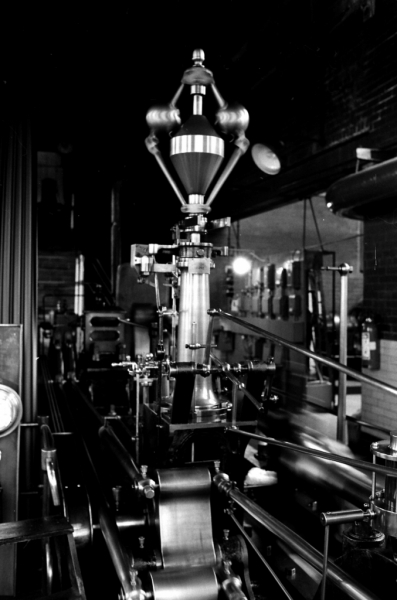
The Lumb governor and Wilby speed regulator on the engine at Bancroft Shed.
SCG/28/07/14