Amateur Radio Homebrew (Shack Culture)
-
PanBiker

- Site Administrator

- Posts: 18215
- Joined: 23 Jan 2012, 13:07
- Location: Barnoldswick - In the West Riding of Yorkshire, always was, always will be.
Re: Amateur Radio Homebrew (Shack Culture)
Ian
-
PanBiker
- Site Administrator
- Posts: 18215
- Joined: 23 Jan 2012, 13:07
- Location: Barnoldswick - In the West Riding of Yorkshire, always was, always will be.
Re: Amateur Radio Homebrew (Shack Culture)
After ordering the Acetal bar, (it may be delivered tomorrow) it was not fit weather wise for doing anything else so I went up into the attic to further the Moxon Antenna build. I thought I would knock a drawing up in Stanley style to show what the plan is.
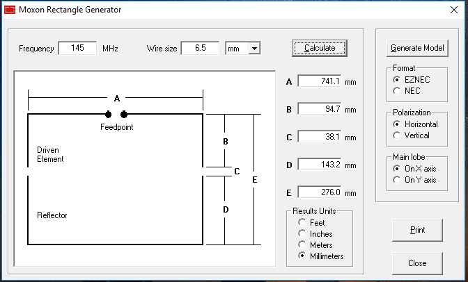
This is the overall design, the front of the antenna is shown at the top. It is basically two half wavelength elements with their ends folded back. The driven element is the one that is directly connected to the transceiver by a feed line. The element at the back is the reflector and is the bit that captures the signal and reflects it to the front element on receive. On transmit, the outgoing signal is fed to the driven element and pushed forwards by the reflector. This arrangement gives the antenna forward gain and directivity. Forward gain also gives you an effective power increase on the outgoing signal. Not going to go into the depths of antenna theory but safe to say that this antenna will be directional and it will shove out more effective radiated power than what you put in.
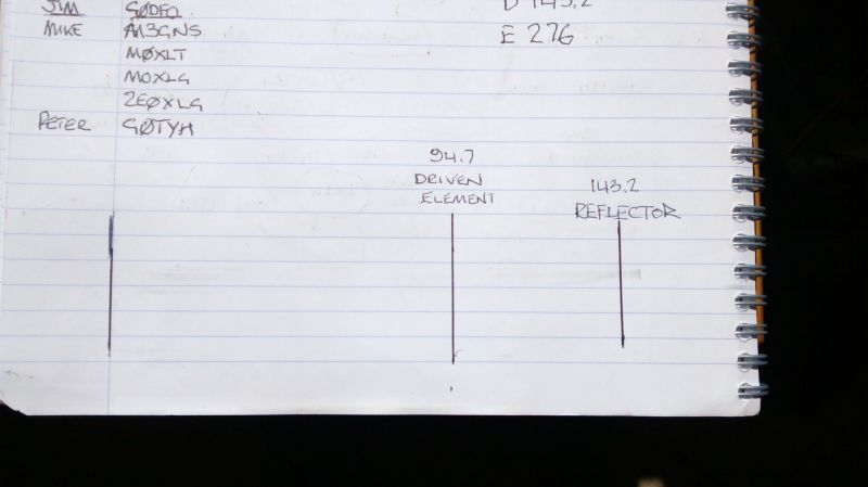
The diagram also shows how I intend to create the driven element dipole centre.
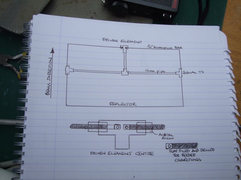
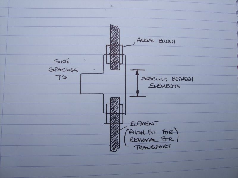
The second diagram shows how the T connectors at the ends of the main spreader will be used to create the required spacing and the elements isolation from one another.
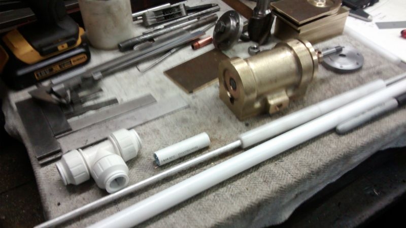
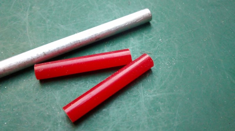
The hub is made from 15mm PVC barrier pipe and a number of equal T connectors, bushes for the T connectors and elements will be formed from Acetal bar, elements will be formed from 1/4" aluminium bar, components shown below.
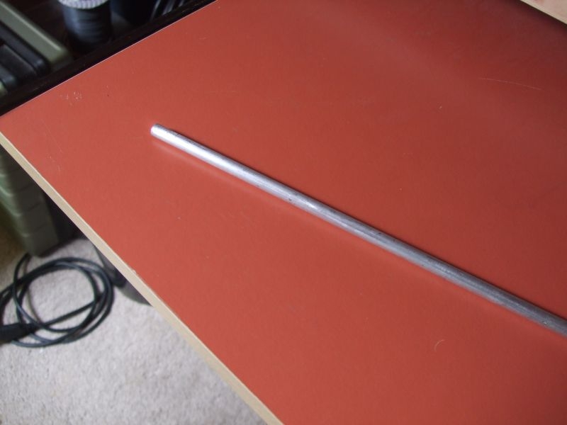
Aluminium Bar
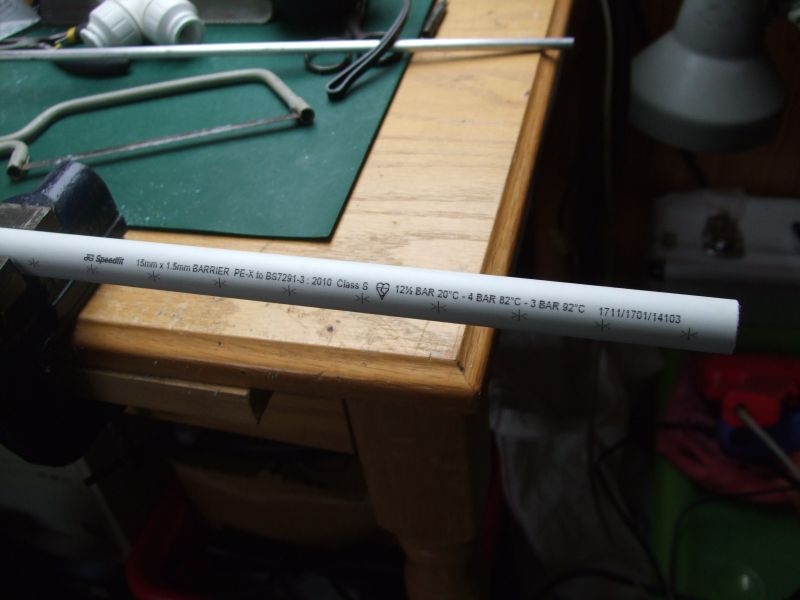
This is the 15mm barrier pipe.
and the JG Speedfit 15mm equal T connectors.
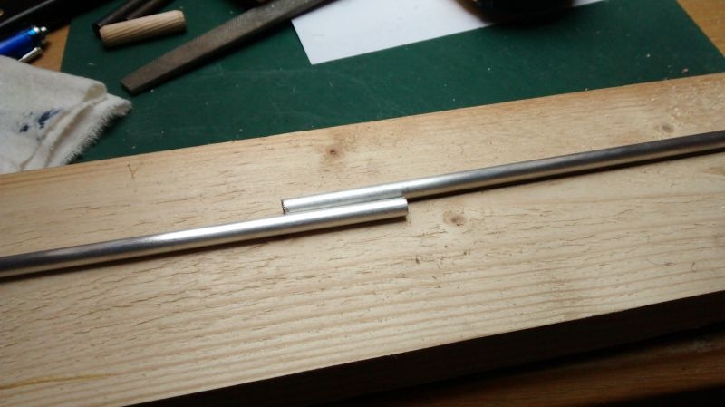
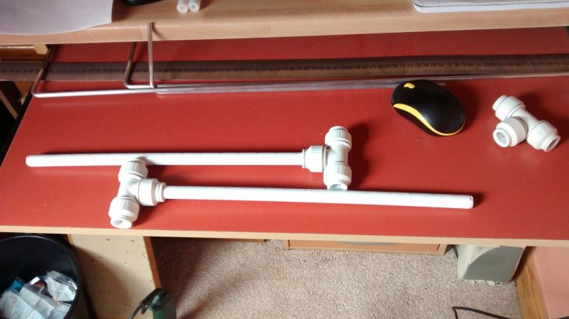
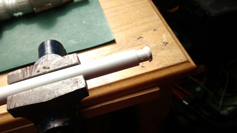
This is the main spreader that I have made so far for the hub. It is slightly oversize in length, I will adjust this to finished length when the elements are fabricated.
The centre connector will connect with another length of pipe to the T connector at the centre of the driven element. This arrangement of hub will create a mounting point for the antenna so that it can be fixed to a pole for portable use.
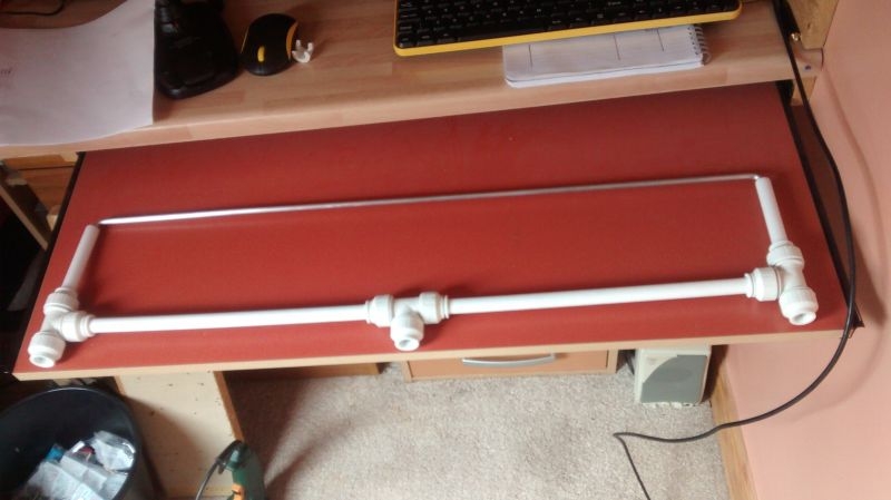
This shows the sizing relationship between the hub components and the elements.
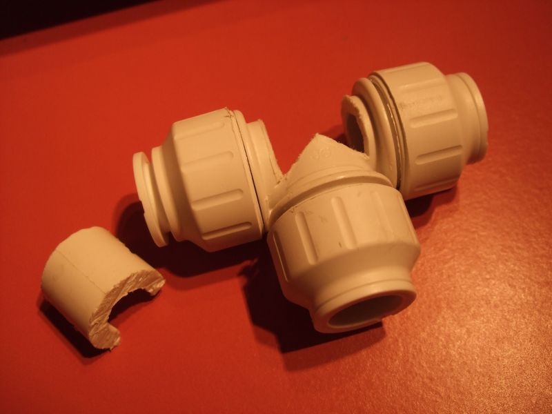
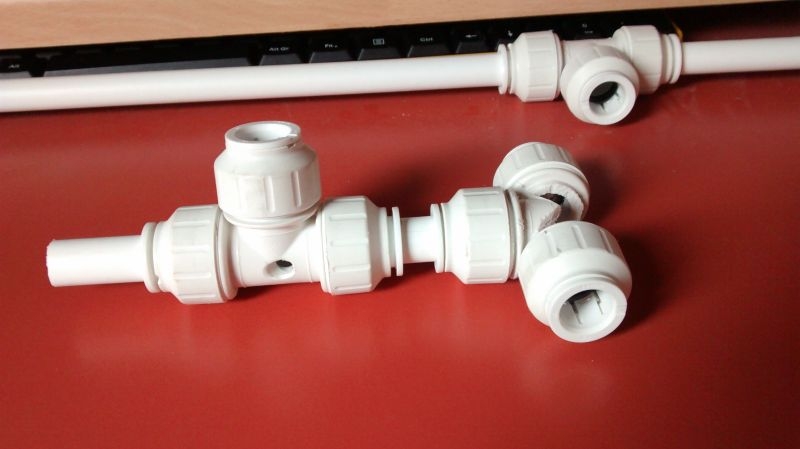
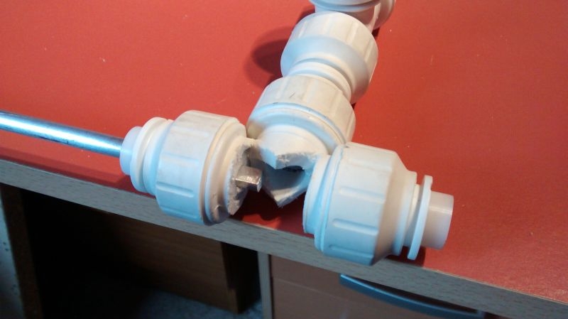
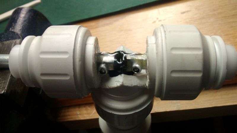
This is making a start on the centre connector for the driven element. I need to gain entry to the centre of the connector to access the ends of each side of the driven element. I intend to file a flat on each bar end and then drill out to accept a pop rivet. The feeder cable will be prepared with crimped and soldered ring connectors on the centre conductor and shield of the cable. I should be able to get in with the end of the pop riveter and make the connections. Once verified as sound I will fill the opened up void with silicone sealant.
Hardest bit here will be cutting the horizontal, if I could get it out as a single piece I could refit it once the joints were made and the void filled with sealant, it would make quite a neat job. The injection moulded T connectors are quite robust, I used a tenon saw to make the vertical cuts. I'll put another picture up later with my success or failure with this.
Later.....
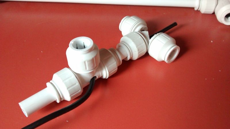
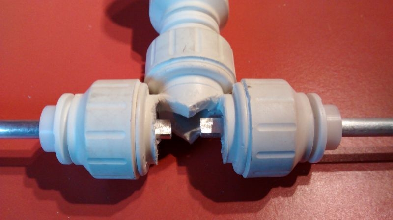
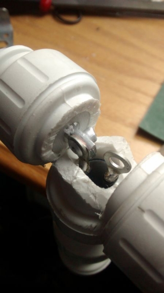
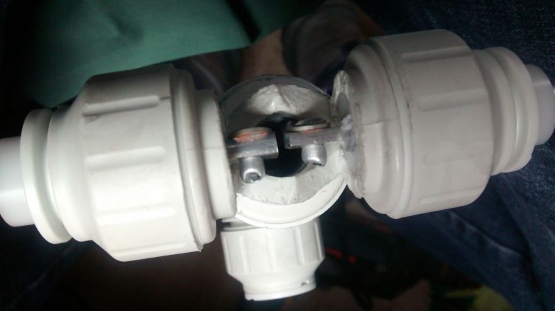
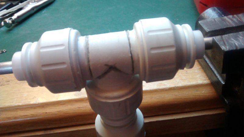
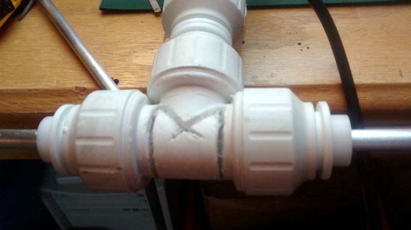
Success, I dug out my high speed rotary tool that I bought a few years back from a garage sale that we came across when driving back from holiday in Wales. I saw this in box of stuff that was on offer, it's about twice the size of a Dremmel and has a fully adjustable speed control, it came with a stand, an umbilical drive and a bunch of tools and collets, I think it cost me all of £5.00. I remembered it had some small rotary saw blades so I tooled it up and used it to follow the contour lines of the moulding, there was just enough room to get the blade in and cut a V at each side to join with the vertical cuts I had made before. It took a while to tease out the cut section but managed in the end with a combination of a very small screwdriver and a Stanley knife to finally separate it from the rest of the moulding, it came out in one piece anyway. I am suited with this but seeing how the internal construction is if I had to do another I would have just gone horizontal. The mouldings are very robust and the plastic is over 4mm thick at this point of the moulding. Pictures are done in artificial light and I must not have had the macro on for the second one but you should see that it should give me enough access.
Looking down from the top
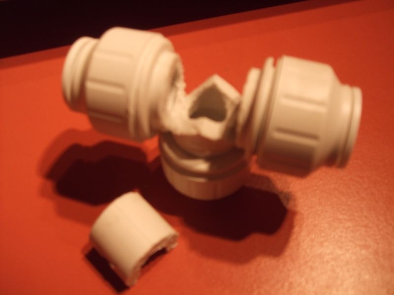
I should not have a problem fitting the cut out back in once it is packed with silicone.
I am a bit vexed as I can't find my blowlamp at the moment, I don't think I took it to Jack's as I had no need for it in the kitchen build. It's in the house somewhere but hiding.
This is the overall design, the front of the antenna is shown at the top. It is basically two half wavelength elements with their ends folded back. The driven element is the one that is directly connected to the transceiver by a feed line. The element at the back is the reflector and is the bit that captures the signal and reflects it to the front element on receive. On transmit, the outgoing signal is fed to the driven element and pushed forwards by the reflector. This arrangement gives the antenna forward gain and directivity. Forward gain also gives you an effective power increase on the outgoing signal. Not going to go into the depths of antenna theory but safe to say that this antenna will be directional and it will shove out more effective radiated power than what you put in.
The diagram also shows how I intend to create the driven element dipole centre.
The second diagram shows how the T connectors at the ends of the main spreader will be used to create the required spacing and the elements isolation from one another.
The hub is made from 15mm PVC barrier pipe and a number of equal T connectors, bushes for the T connectors and elements will be formed from Acetal bar, elements will be formed from 1/4" aluminium bar, components shown below.
Aluminium Bar
This is the 15mm barrier pipe.
and the JG Speedfit 15mm equal T connectors.
This is the main spreader that I have made so far for the hub. It is slightly oversize in length, I will adjust this to finished length when the elements are fabricated.
The centre connector will connect with another length of pipe to the T connector at the centre of the driven element. This arrangement of hub will create a mounting point for the antenna so that it can be fixed to a pole for portable use.
This shows the sizing relationship between the hub components and the elements.
This is making a start on the centre connector for the driven element. I need to gain entry to the centre of the connector to access the ends of each side of the driven element. I intend to file a flat on each bar end and then drill out to accept a pop rivet. The feeder cable will be prepared with crimped and soldered ring connectors on the centre conductor and shield of the cable. I should be able to get in with the end of the pop riveter and make the connections. Once verified as sound I will fill the opened up void with silicone sealant.
Hardest bit here will be cutting the horizontal, if I could get it out as a single piece I could refit it once the joints were made and the void filled with sealant, it would make quite a neat job. The injection moulded T connectors are quite robust, I used a tenon saw to make the vertical cuts. I'll put another picture up later with my success or failure with this.
Later.....
Success, I dug out my high speed rotary tool that I bought a few years back from a garage sale that we came across when driving back from holiday in Wales. I saw this in box of stuff that was on offer, it's about twice the size of a Dremmel and has a fully adjustable speed control, it came with a stand, an umbilical drive and a bunch of tools and collets, I think it cost me all of £5.00. I remembered it had some small rotary saw blades so I tooled it up and used it to follow the contour lines of the moulding, there was just enough room to get the blade in and cut a V at each side to join with the vertical cuts I had made before. It took a while to tease out the cut section but managed in the end with a combination of a very small screwdriver and a Stanley knife to finally separate it from the rest of the moulding, it came out in one piece anyway. I am suited with this but seeing how the internal construction is if I had to do another I would have just gone horizontal. The mouldings are very robust and the plastic is over 4mm thick at this point of the moulding. Pictures are done in artificial light and I must not have had the macro on for the second one but you should see that it should give me enough access.
Looking down from the top
I should not have a problem fitting the cut out back in once it is packed with silicone.
I am a bit vexed as I can't find my blowlamp at the moment, I don't think I took it to Jack's as I had no need for it in the kitchen build. It's in the house somewhere but hiding.
Ian
-
Stanley

- Global Moderator

- Posts: 106092
- Joined: 23 Jan 2012, 12:01
- Location: Barnoldswick. Nearer to Heaven than Gloria.
Re: Amateur Radio Homebrew (Shack Culture)
You know where I am. If you haven't a blowlamp I can give you my old one....
Stanley Challenger Graham
Stanley's View
scg1936 at talktalk.net
"Beware of certitude" (Jimmy Reid)
The floggings will continue until morale improves!
Old age isn't for cissies!
Stanley's View
scg1936 at talktalk.net
"Beware of certitude" (Jimmy Reid)
The floggings will continue until morale improves!
Old age isn't for cissies!
-
PanBiker
- Site Administrator
- Posts: 18215
- Joined: 23 Jan 2012, 13:07
- Location: Barnoldswick - In the West Riding of Yorkshire, always was, always will be.
Re: Amateur Radio Homebrew (Shack Culture)
Thanks Stanley, good to know, mine is only hiding but doing a very good job of it at the moment. 
Better news, I received an email this morning at about 7.30, my plastic stock will be delivered between 10.30 and 11.30 today, I only ordered it yesterday morning, good service still exists in some quarters.
Better news, I received an email this morning at about 7.30, my plastic stock will be delivered between 10.30 and 11.30 today, I only ordered it yesterday morning, good service still exists in some quarters.
Ian
-
PanBiker
- Site Administrator
- Posts: 18215
- Joined: 23 Jan 2012, 13:07
- Location: Barnoldswick - In the West Riding of Yorkshire, always was, always will be.
Re: Amateur Radio Homebrew (Shack Culture)
I have it, delivered at 10.45, 16mm and 10mm Acetal bar. 
Ian
-
Stanley
- Global Moderator
- Posts: 106092
- Joined: 23 Jan 2012, 12:01
- Location: Barnoldswick. Nearer to Heaven than Gloria.
Re: Amateur Radio Homebrew (Shack Culture)
Stanley Challenger Graham
Stanley's View
scg1936 at talktalk.net
"Beware of certitude" (Jimmy Reid)
The floggings will continue until morale improves!
Old age isn't for cissies!
Stanley's View
scg1936 at talktalk.net
"Beware of certitude" (Jimmy Reid)
The floggings will continue until morale improves!
Old age isn't for cissies!
-
PanBiker
- Site Administrator
- Posts: 18215
- Joined: 23 Jan 2012, 13:07
- Location: Barnoldswick - In the West Riding of Yorkshire, always was, always will be.
Re: Amateur Radio Homebrew (Shack Culture)
I took the Acetal bar down to Stanley for machining to size and boring out for the elements. Here he is engaged in a session of piecework for me.
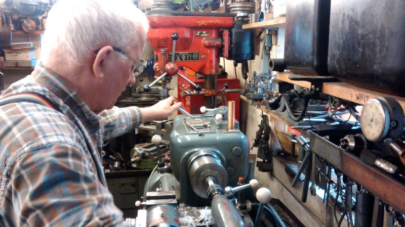
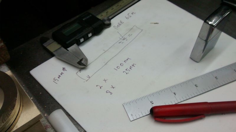
Job was to make two bushes 100mm long and another two roughly the same size for me to cut down as required for the shorter bushes. Stock bar was 16mm + tolerance which had to be reduced to 15mm and then centre drilled out at 6.5mm which the elements turned out to be. Here is Stanley's fag packet drawing for the job in hand, modified slightly regarding the 8 x 25mm.
Finished bushes in among Stanley's latest engine parts.
Job done in about an hour and I came away with all I need now to complete the antenna. I hunted high and low for my blow lamp and still cant find it so I have taken Stanley up on his offer of his old one, (bet I find mine now).
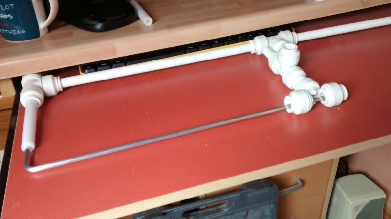
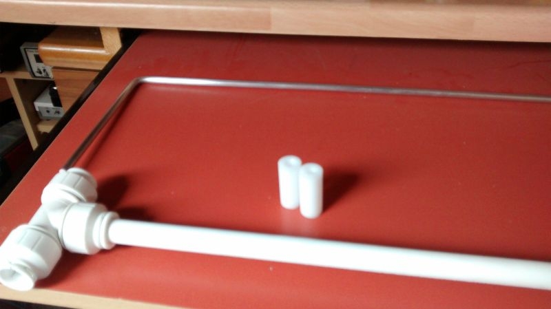
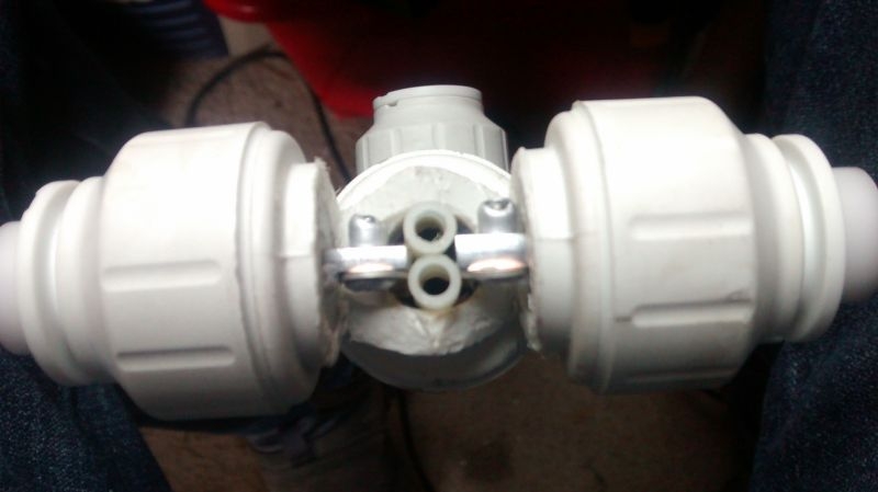
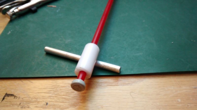
I had a bit of dinner and then took my newly formed goodies upstairs to further the build. I first set about putting the hub extension together that will support the driven element of the antenna and provide a mounting point. The extension from the centre of the hub is just another two T connectors, one for the dipole centre which I have made the entry into and another in the centre which will act as a mount for on a mast. I cut two lengths of barrier pipe 30mm long to join the T's together. Image shows the arrangement upside down without the main connection into the main spreader, I need to keep it separate for the moment so that I can make the dipole centre. I have drilled a cable egress point in the centre T for the feeder cable.
Here it is with the cable routed through,
Time to bite the bullet now and bend some metal. I didn't have any Imperial Leather soap as advised but fortunately our local Post Office has it on offer, 3 bars for £1 so I nipped out to get some. Armed with our temperature indicator we are ready to proceed. I knocked up a bending jig on a spare piece of timber that I had using a couple of drill bits, one for the bending radius and the other as a back stop for the bending operation. I just drilled the relevant holes all the way through the timber and then shoved the bits in upside down to use the shanks. I marked a starting position for the end of the element and a line at right angles to indicate how far to take the bend.
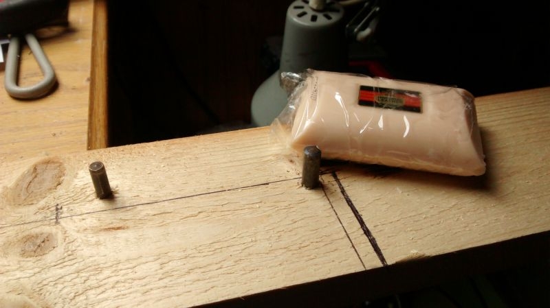
I decided to tackle the driven element first as this is made in two halves. All that was required was to create a single 90 degree bend in each element leg ensuring that it allowed trimming leeway on both legs of the angle. I cleaned up the bar with wire wool applied the soap at the required position, heated till the soap turned black and then went for the bend. You can see the discoloured soap on the bend and the fact that I got a bit close during heating, angle looks good though.
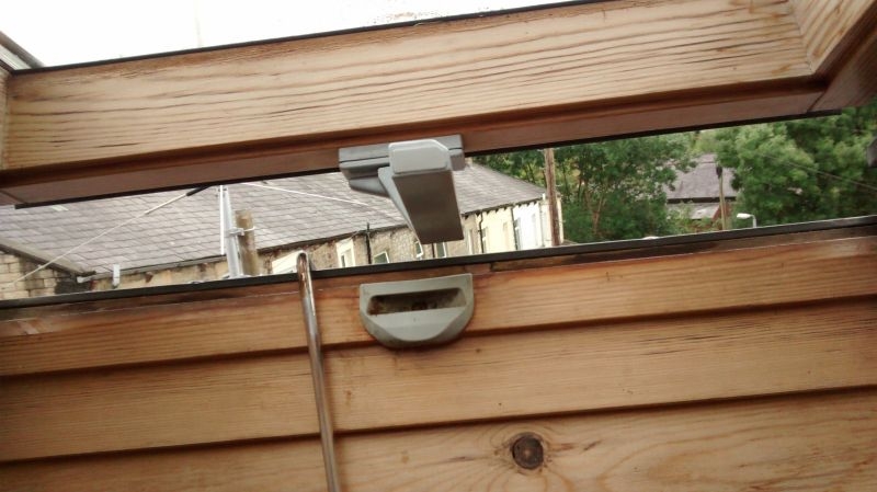
I hung the element out of the Velux to cool down.
A quick clean up with the wire wool and the bend looks OK, no stressing apparent so it looks like I got the annealing temperature right.
I pressed on with the second one taking care to heat the bend away from the bending jig! I marked the jig up for the overall length of the finished element so that I could check for the correct leg lengths.
Plenty of overlap in the centre I can cut this exactly as I need it for the centre connections, there is about 8mm spare on each of the shorter legs so these can be trimmed back exactly before final assembly. If you look at the dimensions you will see that millimetre precision is required on element dimensions. All lengths and spacings are critical as these control the resonant frequency of the antenna and the impedance matching for the driven element.
Both sides of the dipole made it was time to offer one side up to the hub with one of the 100mm bushes to check that all my sizing calculations are good. I need to use a particularly long bush for the driven element to cater for the centre T connector in the hub extension, it's looking good. The centre of the driven element will have shorter bushes at either side as will the connectors on the reflector side of the antenna.
That's a far as I got today and I am quite pleased with the progress, the antenna should turn out to be very robust when it is completed. Next job will be making the reflector which is all in one piece, two bends and a critical dimension to get right.
Job was to make two bushes 100mm long and another two roughly the same size for me to cut down as required for the shorter bushes. Stock bar was 16mm + tolerance which had to be reduced to 15mm and then centre drilled out at 6.5mm which the elements turned out to be. Here is Stanley's fag packet drawing for the job in hand, modified slightly regarding the 8 x 25mm.
Finished bushes in among Stanley's latest engine parts.
Job done in about an hour and I came away with all I need now to complete the antenna. I hunted high and low for my blow lamp and still cant find it so I have taken Stanley up on his offer of his old one, (bet I find mine now).
I had a bit of dinner and then took my newly formed goodies upstairs to further the build. I first set about putting the hub extension together that will support the driven element of the antenna and provide a mounting point. The extension from the centre of the hub is just another two T connectors, one for the dipole centre which I have made the entry into and another in the centre which will act as a mount for on a mast. I cut two lengths of barrier pipe 30mm long to join the T's together. Image shows the arrangement upside down without the main connection into the main spreader, I need to keep it separate for the moment so that I can make the dipole centre. I have drilled a cable egress point in the centre T for the feeder cable.
Here it is with the cable routed through,
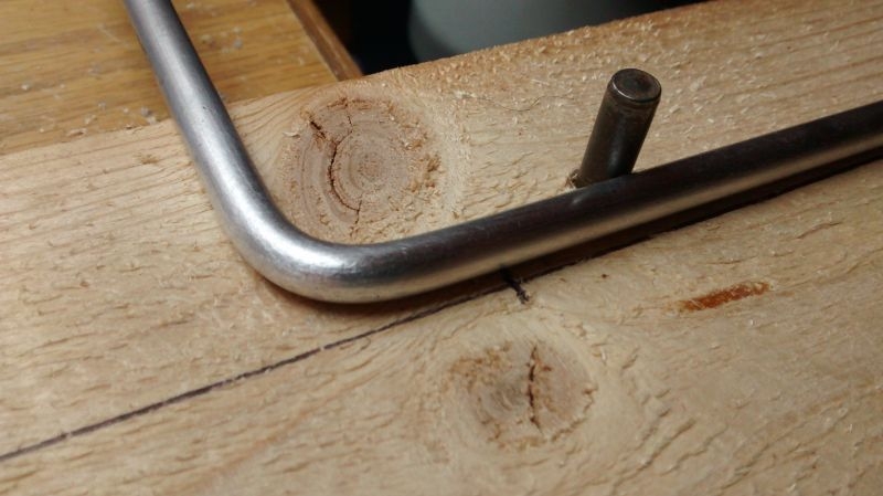
Time to bite the bullet now and bend some metal. I didn't have any Imperial Leather soap as advised but fortunately our local Post Office has it on offer, 3 bars for £1 so I nipped out to get some. Armed with our temperature indicator we are ready to proceed. I knocked up a bending jig on a spare piece of timber that I had using a couple of drill bits, one for the bending radius and the other as a back stop for the bending operation. I just drilled the relevant holes all the way through the timber and then shoved the bits in upside down to use the shanks. I marked a starting position for the end of the element and a line at right angles to indicate how far to take the bend.
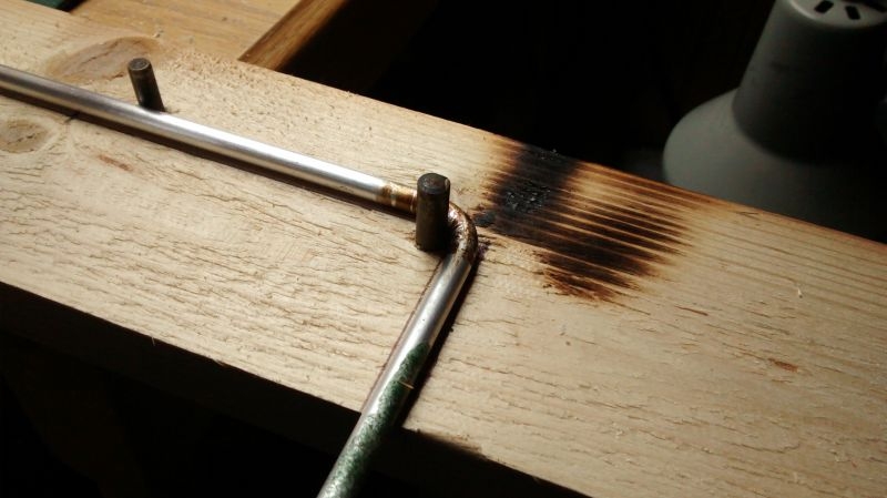
I decided to tackle the driven element first as this is made in two halves. All that was required was to create a single 90 degree bend in each element leg ensuring that it allowed trimming leeway on both legs of the angle. I cleaned up the bar with wire wool applied the soap at the required position, heated till the soap turned black and then went for the bend. You can see the discoloured soap on the bend and the fact that I got a bit close during heating, angle looks good though.
I hung the element out of the Velux to cool down.
A quick clean up with the wire wool and the bend looks OK, no stressing apparent so it looks like I got the annealing temperature right.
I pressed on with the second one taking care to heat the bend away from the bending jig! I marked the jig up for the overall length of the finished element so that I could check for the correct leg lengths.
Plenty of overlap in the centre I can cut this exactly as I need it for the centre connections, there is about 8mm spare on each of the shorter legs so these can be trimmed back exactly before final assembly. If you look at the dimensions you will see that millimetre precision is required on element dimensions. All lengths and spacings are critical as these control the resonant frequency of the antenna and the impedance matching for the driven element.
Both sides of the dipole made it was time to offer one side up to the hub with one of the 100mm bushes to check that all my sizing calculations are good. I need to use a particularly long bush for the driven element to cater for the centre T connector in the hub extension, it's looking good. The centre of the driven element will have shorter bushes at either side as will the connectors on the reflector side of the antenna.
That's a far as I got today and I am quite pleased with the progress, the antenna should turn out to be very robust when it is completed. Next job will be making the reflector which is all in one piece, two bends and a critical dimension to get right.
Ian
-
Stanley
- Global Moderator
- Posts: 106092
- Joined: 23 Jan 2012, 12:01
- Location: Barnoldswick. Nearer to Heaven than Gloria.
Re: Amateur Radio Homebrew (Shack Culture)
I am on my last bar of Imperial Leather, I shall pop into the PO!
Stanley Challenger Graham
Stanley's View
scg1936 at talktalk.net
"Beware of certitude" (Jimmy Reid)
The floggings will continue until morale improves!
Old age isn't for cissies!
Stanley's View
scg1936 at talktalk.net
"Beware of certitude" (Jimmy Reid)
The floggings will continue until morale improves!
Old age isn't for cissies!
-
PanBiker
- Site Administrator
- Posts: 18215
- Joined: 23 Jan 2012, 13:07
- Location: Barnoldswick - In the West Riding of Yorkshire, always was, always will be.
Re: Amateur Radio Homebrew (Shack Culture)
It's on the left hand side where you queue for the tills.
A bit more on the dimensions of the antenna. It is actually the driven element of an array that determines the resonant frequency but in this design the reflector is the determining factor. The resonant frequency is where the antenna will operate at optimum performance. As the antenna will be operated horizontally, I have chosen the resonant frequency to be in the centre of the SSB (Single Side Band) portion of the 2M band, (transmissions here use horizontal propagation)
The reflector is a single length of aluminium bar, the position of the two right angles required will determine the finished width of the element and therefore the resonant frequency of the array. I have purposely left the width of the hub oversize and made the two halves of the driven element with extra length to play with so that I can match to two sides of the design as accurately as possible within the tolerances of the materials used for the design. Once the reflector is finalised I can alter the hub width to suite and then set the driven element to exactly the same dimension.
Weather is not up to much at all today so it looks like I might get to play a little bit more with the build before the day is out.
Ian
-
PanBiker
- Site Administrator
- Posts: 18215
- Joined: 23 Jan 2012, 13:07
- Location: Barnoldswick - In the West Riding of Yorkshire, always was, always will be.
Re: Amateur Radio Homebrew (Shack Culture)
Onward with the build this afternoon, I first cut the required length of bar for the reflector, the length of this element all in one piece determined that I needed to move the bending rig. I had to pull it back along the bench at a diagonal where it was a bit unstable so secured it to the bench with a couple of screws, don't want that wandering around with 600 degrees hot metal in the jig. I calculated the length of the legs and marked up the jig with a new indicator for the end of the element. I bent the first leg which was no problem apart from the fact that I triggered the linked smoke alarms, I opened the Velux and they soon cleared. I turned it round and set it against a couple of stops installed at the far end. It has to be kept flat for the second bend so that each leg is aligned horizontally.
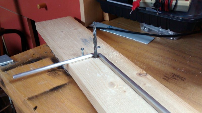
I put another stop screw about half way along the length of the element to stop it bowing out on the next bend. I left the far end in the jig and propped the other end up so that I could heat it clear of the jig. Once temperature had been reached I lowered it quickly into the bending pegs and completed the other leg, I shoved it out of the Velux to cool and then cleaned it up before popping it back in the jig. You can see that I made a slight miscalculation on the leg lengths, not quite balanced but enough length in the shortest one so all OK.
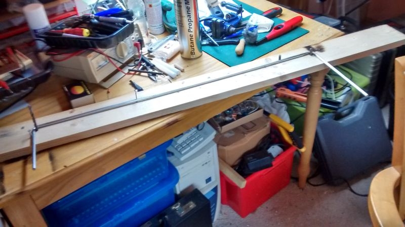
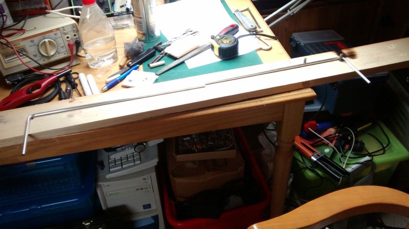
Offering it up to the ruler to see what the final dimension is, as it turns out it is slightly too short at just over 741mm, a little over 3mm short, this will have a knock on effect for all the other dimensions and will slightly alter the resonant frequency.
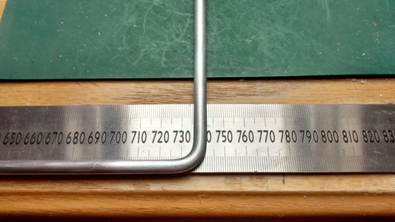
With the reflector turning out slightly short we have to recalculate for the new dimensions. The frequency comes out at 145MHz which is actually exactly in the middle of the 2M amateur band which spans 144MHz to 146MHz. It is 700Khz higher than before, it isn't a disaster it just means that it will operate at optimum in the centre of the band. The design is quite broadband so it will still be OK at both sides of the resonant frequency. The main knock on for the build is that all the other dimensions are altered slightly, this is only in the overall width of the hub and the lengths of the turned back legs of the elements, all of these have not been cut yet so it is no problem.
I measured out a cutting crib for the driven element and reflector legs, offered up the relative element parts and cut them all down to final size. I filed the ends flat and broke the edges.
Next job was to reduce the width of the hub to match the finished element lengths. I measured it up before disassembly and it was exactly 800mm centre to centre of the end T connectors. 30mm per leg to loose to get it down to 740mm. I split each leg from the centre T connector.
Into the vice, take out the pipe insert and cut down, replace insert and rebuild the hub.
I checked the newly built hub which was correct at 740mm then used the 100mm bushes to check the fitting of the reflector to the hub.
The 100mm bushes are for the driven element side so I made smaller 35mm bushes for the reflector from the other lengths that Stanley sorted yesterday. That completes the construction for the reflector side of the array.
On now to the driven element. I cut two more 35mm bushes for the centre of the driven element T connector and then offered both legs of the element up to check how much overlap I had. I marked the exact centre from the middle of the hub which left each leg length at 370mm. We need a small gap in the middle to create the dipole so I reduced each leg by a further 3mm. I will be fastening the coax feeder cable with pop rivets so I need a flat filing on each leg of the dipole.
With bushes now inserted I checked the positioning of the flat within the connector.
Second element leg done and checking for the gap I will have in the middle, looks OK. Once the cable is fitted I will insert an insulating block between the legs so there is no chance of the legs shorting.
Coming together quite nicely now, next job will be drilling out and fitting the feeder cable.
I put another stop screw about half way along the length of the element to stop it bowing out on the next bend. I left the far end in the jig and propped the other end up so that I could heat it clear of the jig. Once temperature had been reached I lowered it quickly into the bending pegs and completed the other leg, I shoved it out of the Velux to cool and then cleaned it up before popping it back in the jig. You can see that I made a slight miscalculation on the leg lengths, not quite balanced but enough length in the shortest one so all OK.
Offering it up to the ruler to see what the final dimension is, as it turns out it is slightly too short at just over 741mm, a little over 3mm short, this will have a knock on effect for all the other dimensions and will slightly alter the resonant frequency.
With the reflector turning out slightly short we have to recalculate for the new dimensions. The frequency comes out at 145MHz which is actually exactly in the middle of the 2M amateur band which spans 144MHz to 146MHz. It is 700Khz higher than before, it isn't a disaster it just means that it will operate at optimum in the centre of the band. The design is quite broadband so it will still be OK at both sides of the resonant frequency. The main knock on for the build is that all the other dimensions are altered slightly, this is only in the overall width of the hub and the lengths of the turned back legs of the elements, all of these have not been cut yet so it is no problem.
I measured out a cutting crib for the driven element and reflector legs, offered up the relative element parts and cut them all down to final size. I filed the ends flat and broke the edges.
Next job was to reduce the width of the hub to match the finished element lengths. I measured it up before disassembly and it was exactly 800mm centre to centre of the end T connectors. 30mm per leg to loose to get it down to 740mm. I split each leg from the centre T connector.
Into the vice, take out the pipe insert and cut down, replace insert and rebuild the hub.
I checked the newly built hub which was correct at 740mm then used the 100mm bushes to check the fitting of the reflector to the hub.
The 100mm bushes are for the driven element side so I made smaller 35mm bushes for the reflector from the other lengths that Stanley sorted yesterday. That completes the construction for the reflector side of the array.
On now to the driven element. I cut two more 35mm bushes for the centre of the driven element T connector and then offered both legs of the element up to check how much overlap I had. I marked the exact centre from the middle of the hub which left each leg length at 370mm. We need a small gap in the middle to create the dipole so I reduced each leg by a further 3mm. I will be fastening the coax feeder cable with pop rivets so I need a flat filing on each leg of the dipole.
With bushes now inserted I checked the positioning of the flat within the connector.
Second element leg done and checking for the gap I will have in the middle, looks OK. Once the cable is fitted I will insert an insulating block between the legs so there is no chance of the legs shorting.
Coming together quite nicely now, next job will be drilling out and fitting the feeder cable.
Ian
-
Stanley
- Global Moderator
- Posts: 106092
- Joined: 23 Jan 2012, 12:01
- Location: Barnoldswick. Nearer to Heaven than Gloria.
Re: Amateur Radio Homebrew (Shack Culture)
Stanley Challenger Graham
Stanley's View
scg1936 at talktalk.net
"Beware of certitude" (Jimmy Reid)
The floggings will continue until morale improves!
Old age isn't for cissies!
Stanley's View
scg1936 at talktalk.net
"Beware of certitude" (Jimmy Reid)
The floggings will continue until morale improves!
Old age isn't for cissies!
-
PanBiker
- Site Administrator
- Posts: 18215
- Joined: 23 Jan 2012, 13:07
- Location: Barnoldswick - In the West Riding of Yorkshire, always was, always will be.
Re: Amateur Radio Homebrew (Shack Culture)
Not a lot of time today for the antenna. I had to recover my drill set from our Jacks and then found that we had been invited out for tea at our Carla's. Silsden Gala to visit first though so I only had an hour or so.
I thought I would get the element drilling done first so pressed on. The rivets are 3.3mm so I needed to be fairly accurate with the centre punching in 6.5mm bar. I got it wrong first time so filed my mistake out and had another go, better the second time. I drilled out with a 3mm drill first and then hand filed out with a little rat tailed to get a nice fit for the rivet.
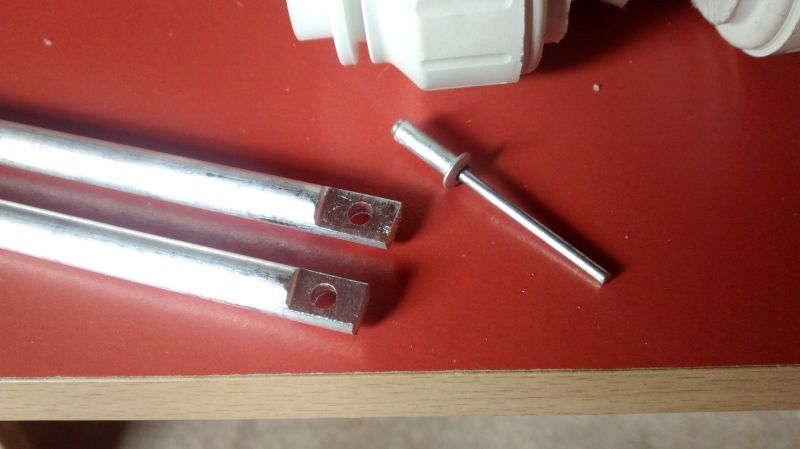
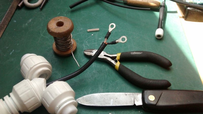
I pressed on with cable preparation, I am using what I have left of a reel of UR43 cable. It's not the best choice for a cable for a portable antenna as it has a solid core and is not quite as flexible as a cable with a stranded centre, it's not stiff by any means. I don't have a choice of any other so it will be used and will be perfectly serviceable for the job. There is just about 3.5m left on the reel, just right for this job but no good for anything else. Here it is fed through the T and with about 1.5" of outer jacket removed.
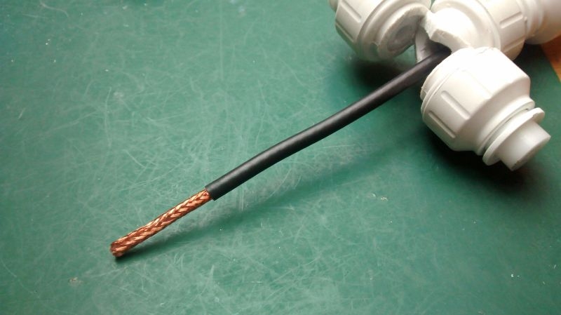
I teased out the braided outer and re-twisted into a single conductor. I decided to solder the connections rather than crimp them so I tinned the braid. I had to file the tinned lead slightly to get it into the connector but it made a nice snug fit and was easy enough to solder up. I had already fitted the lead with a bit of heat shrink so finished that off with the heat gun. The centre conductor has its own insulation of course and solid copper core so no problem trimming that back tinning and soldering up. I put heat shrink on that as well, no real point, probably force of habit. Anyway the cable is sorted now and ready for assembly to the driven element.
I thought I would get the element drilling done first so pressed on. The rivets are 3.3mm so I needed to be fairly accurate with the centre punching in 6.5mm bar. I got it wrong first time so filed my mistake out and had another go, better the second time. I drilled out with a 3mm drill first and then hand filed out with a little rat tailed to get a nice fit for the rivet.
I pressed on with cable preparation, I am using what I have left of a reel of UR43 cable. It's not the best choice for a cable for a portable antenna as it has a solid core and is not quite as flexible as a cable with a stranded centre, it's not stiff by any means. I don't have a choice of any other so it will be used and will be perfectly serviceable for the job. There is just about 3.5m left on the reel, just right for this job but no good for anything else. Here it is fed through the T and with about 1.5" of outer jacket removed.
I teased out the braided outer and re-twisted into a single conductor. I decided to solder the connections rather than crimp them so I tinned the braid. I had to file the tinned lead slightly to get it into the connector but it made a nice snug fit and was easy enough to solder up. I had already fitted the lead with a bit of heat shrink so finished that off with the heat gun. The centre conductor has its own insulation of course and solid copper core so no problem trimming that back tinning and soldering up. I put heat shrink on that as well, no real point, probably force of habit. Anyway the cable is sorted now and ready for assembly to the driven element.
Ian

Re: Amateur Radio Homebrew (Shack Culture)
Coming along nicely.
I wondered what the gain of this antenna might be, so did a quick google and found this
Gain of Moxon Antenna
There seems to be some difference of opinion. I always thought that "antennas and propagation " was a bit of a black art. I think I still do.
I wondered what the gain of this antenna might be, so did a quick google and found this
Gain of Moxon Antenna
There seems to be some difference of opinion. I always thought that "antennas and propagation " was a bit of a black art. I think I still do.
Born to be mild
Sapere Aude
Ego Lego
Preferred pronouns - Thou, Thee, Thy, Thine
My non-working days are Monday - Sunday
Sapere Aude
Ego Lego
Preferred pronouns - Thou, Thee, Thy, Thine
My non-working days are Monday - Sunday
-
Stanley
- Global Moderator
- Posts: 106092
- Joined: 23 Jan 2012, 12:01
- Location: Barnoldswick. Nearer to Heaven than Gloria.
Re: Amateur Radio Homebrew (Shack Culture)
I don't even know what propagation means in this context......
Stanley Challenger Graham
Stanley's View
scg1936 at talktalk.net
"Beware of certitude" (Jimmy Reid)
The floggings will continue until morale improves!
Old age isn't for cissies!
Stanley's View
scg1936 at talktalk.net
"Beware of certitude" (Jimmy Reid)
The floggings will continue until morale improves!
Old age isn't for cissies!
-
PanBiker
- Site Administrator
- Posts: 18215
- Joined: 23 Jan 2012, 13:07
- Location: Barnoldswick - In the West Riding of Yorkshire, always was, always will be.
Re: Amateur Radio Homebrew (Shack Culture)
Indeed Tripps the main Crib site for the Moxon is here and claims 5.5dbi forward gain and 25db front to back ratio.
Moxon Antenna Project
There are many variable factors that come into play when calculating the figures for any given antenna, all are supposed to be calculated against a basic dipole assumed to have no losses.
Size of antenna, methods of construction and materials used, height deployed above ground and even the conductivity factor of that said ground are just a few of the factors that will influence the final results. Various classic antenna designs have been analysed over many years so you do get an accepted baseline for achievable efficiency as a guide or to work from. Proof of the pudding is in the working, build it the best you can shove it up and see if it gives you better performance, part of the fascination of building them in the first place.
Of course folk who just buy ready made stuff believing all the claims attached to some of the designs must have more money than sense and in my view are missing out on on section of the hobby that can give a lot of satisfaction. I appreciate also that some of the larger arrays cannot really be built on the kitchen table or in the average workshop but there are thousands of simple designs perfectly achievable with basic tools.
My main antenna for the HF bands, (featured earlier in this thread) is 20M of wire fasted to a small toroid transformer 20ft off the ground between my chimney stack and a neighbours gable wall. It's not as efficient as a 5 element HF beam on a 100ft tower with a £700 rotator to turn it round but it still does allow me to talk to stations on most continents of the earth.
This little offering I am building has cost me just over £20.00 to build, (using a ruler, hacksaw, drill and blowlamp) and I know for a fact that it will be better than the 6" rubber ducky or 12" whip antenna that is on my hand held transceiver. So, apart from the fun of building it will give advantage in stations heard and contacted from the top of the hill.
Ian
-
PanBiker
- Site Administrator
- Posts: 18215
- Joined: 23 Jan 2012, 13:07
- Location: Barnoldswick - In the West Riding of Yorkshire, always was, always will be.
Re: Amateur Radio Homebrew (Shack Culture)
Furthering the antenna build I continued with the driven element and offered the first element leg up for riveting, it was tight but I managed to get in with the gun.
Second one terminated.
The elements definitely need some form of spacer to insulate one from the other so I tried a couple of short plastic tubes from my £1 rally bag of assorted plastic bits.
The plastic tubes weren't very good so I swapped them out for a small compressed rubber boot which held in place a lot better. I mixed a bit of Araldite rapid up and coated the element end where they come through the bushes and the centre insulator to make sure it doesn't move.
Ian
-
PanBiker
- Site Administrator
- Posts: 18215
- Joined: 23 Jan 2012, 13:07
- Location: Barnoldswick - In the West Riding of Yorkshire, always was, always will be.
Re: Amateur Radio Homebrew (Shack Culture)
I retrieved my clear silicone from our Jacks and filled the termination void in the driven element and popped the lid back on, makes quite a neat finish which will be fully waterproof.
I now have to create and maintain 38mm gap between each end of the driven element and the reflector. I am thinking of using a plastic knitting needle cut to exact size to insert inside the drilled out bushes. I can then fix each element permanently in place . This alters the final impedance of the antenna and brings it to 50ohms that is standard for all transceivers. I will then be able to put it under test. The design may need the creation of a common mode choke on the feeder cable, I cant determine this until I do the testing.
I now have to create and maintain 38mm gap between each end of the driven element and the reflector. I am thinking of using a plastic knitting needle cut to exact size to insert inside the drilled out bushes. I can then fix each element permanently in place . This alters the final impedance of the antenna and brings it to 50ohms that is standard for all transceivers. I will then be able to put it under test. The design may need the creation of a common mode choke on the feeder cable, I cant determine this until I do the testing.
Ian
-
Stanley
- Global Moderator
- Posts: 106092
- Joined: 23 Jan 2012, 12:01
- Location: Barnoldswick. Nearer to Heaven than Gloria.
Re: Amateur Radio Homebrew (Shack Culture)
I have some hard PVC type plastic Ian big enough to make 38mm if that would be better....
Stanley Challenger Graham
Stanley's View
scg1936 at talktalk.net
"Beware of certitude" (Jimmy Reid)
The floggings will continue until morale improves!
Old age isn't for cissies!
Stanley's View
scg1936 at talktalk.net
"Beware of certitude" (Jimmy Reid)
The floggings will continue until morale improves!
Old age isn't for cissies!
-
PanBiker
- Site Administrator
- Posts: 18215
- Joined: 23 Jan 2012, 13:07
- Location: Barnoldswick - In the West Riding of Yorkshire, always was, always will be.
Re: Amateur Radio Homebrew (Shack Culture)
As long as its waterproof and a good insulator it doesn't really matter what it is made of it is just a spacer. That's why I thought of a knitting needle, it doesn't even have to be a tight fit its only taking up room in the bore. I have some 10mm Acetal but it seems a shame to cut into a full length to knock that down just for the sake of it.
It needs to be the same size as the bore in the bushes so 6.5mm max and exactly 38mm long x 2. Or if in one piece say 80mm to allow for cutting.
It needs to be the same size as the bore in the bushes so 6.5mm max and exactly 38mm long x 2. Or if in one piece say 80mm to allow for cutting.
Ian
-
Stanley
- Global Moderator
- Posts: 106092
- Joined: 23 Jan 2012, 12:01
- Location: Barnoldswick. Nearer to Heaven than Gloria.
Re: Amateur Radio Homebrew (Shack Culture)
You know where I am if you change your mind.....
Stanley Challenger Graham
Stanley's View
scg1936 at talktalk.net
"Beware of certitude" (Jimmy Reid)
The floggings will continue until morale improves!
Old age isn't for cissies!
Stanley's View
scg1936 at talktalk.net
"Beware of certitude" (Jimmy Reid)
The floggings will continue until morale improves!
Old age isn't for cissies!
-
PanBiker
- Site Administrator
- Posts: 18215
- Joined: 23 Jan 2012, 13:07
- Location: Barnoldswick - In the West Riding of Yorkshire, always was, always will be.
Re: Amateur Radio Homebrew (Shack Culture)
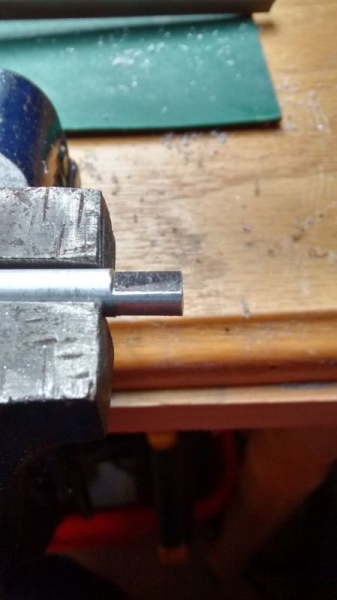
Sally had some sacrificial No 3 knitting needles, just the right size for the bushes.
I cut them to just under 40mm then filed them down to the 38mm needed for the spacing and impedance matching.
I just need to devise a method of fixing the elements in position within the bushes, ideally without introducing any metal. I may have a go with heat shrink sleeving. It would need to be over 15mm to fit over the bushes and shrink to 6.5mm for the elements although I could build up the diameter there with a few layers of insulation tape if required.
Ian
-
PanBiker
- Site Administrator
- Posts: 18215
- Joined: 23 Jan 2012, 13:07
- Location: Barnoldswick - In the West Riding of Yorkshire, always was, always will be.
Re: Amateur Radio Homebrew (Shack Culture)
I have heat shrink tubing in various sizes but sods law says that not to the size or spec that I need! I have ordered up some 4:1 ratio adhesive lined heat shrink tubing, not expensive and should be fit for the job. It should come in the next couple of days.
I may cut up the spare bit of Acetal bushing that I have left just to extend the bushes on the driven element slightly, it will give more area to grip with the heat shrink. Acetal is quite slippery so I think I might put a turn or two of insulation tape round the bushes first and maybe score it to give a surface for grip. The adhesive in the heat shrink activates at the same temperature needed to shrink the tube. It should finish off quite nicely.
I may cut up the spare bit of Acetal bushing that I have left just to extend the bushes on the driven element slightly, it will give more area to grip with the heat shrink. Acetal is quite slippery so I think I might put a turn or two of insulation tape round the bushes first and maybe score it to give a surface for grip. The adhesive in the heat shrink activates at the same temperature needed to shrink the tube. It should finish off quite nicely.
Ian
-
PanBiker
- Site Administrator
- Posts: 18215
- Joined: 23 Jan 2012, 13:07
- Location: Barnoldswick - In the West Riding of Yorkshire, always was, always will be.
Re: Amateur Radio Homebrew (Shack Culture)
Update to the insulation tape idea. I tried some double sided tape on the spare bit of Acetal last night and was quite impressed by the adhesion to it, so much so that I had to use my penknife to help get it off after the test! It should certainly provide enough grip for the job in hand.
Ian
-
Stanley
- Global Moderator
- Posts: 106092
- Joined: 23 Jan 2012, 12:01
- Location: Barnoldswick. Nearer to Heaven than Gloria.
Re: Amateur Radio Homebrew (Shack Culture)
Stanley Challenger Graham
Stanley's View
scg1936 at talktalk.net
"Beware of certitude" (Jimmy Reid)
The floggings will continue until morale improves!
Old age isn't for cissies!
Stanley's View
scg1936 at talktalk.net
"Beware of certitude" (Jimmy Reid)
The floggings will continue until morale improves!
Old age isn't for cissies!