The anti-static mat turned up the day after my last post so I have started the repair steady away. As you will see later I have run into a slight problem.
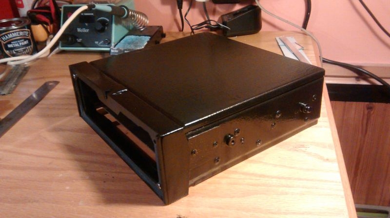
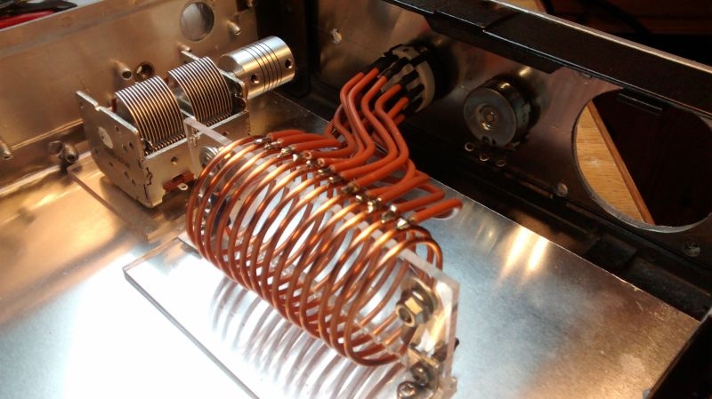
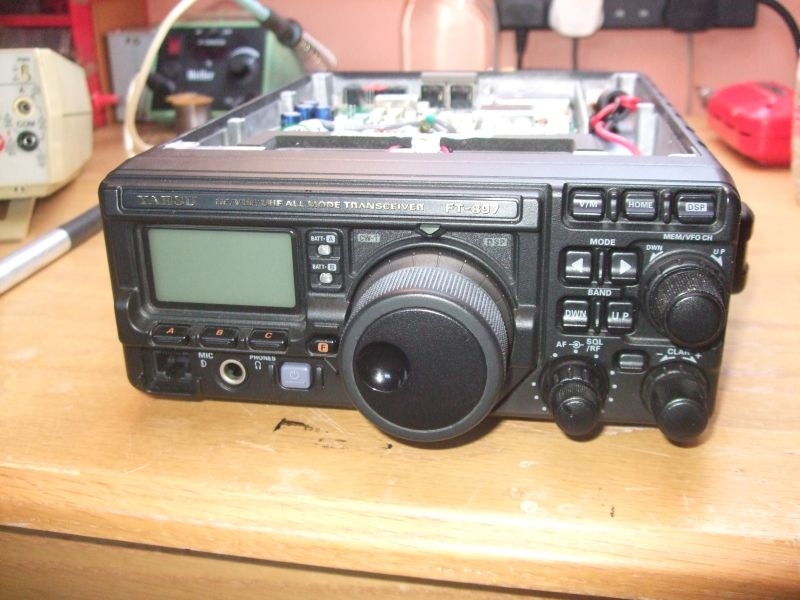
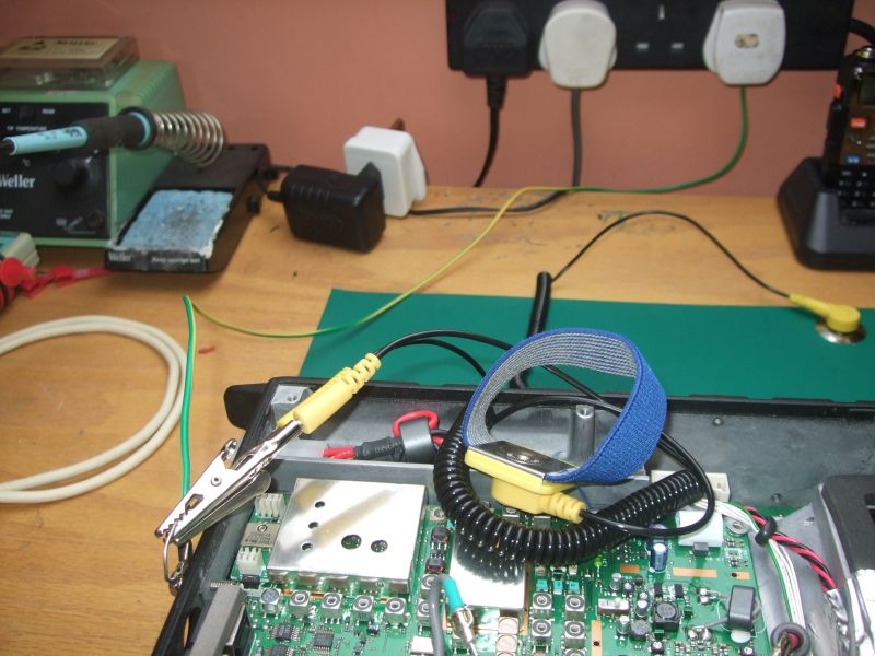
First of all here is the transceiver on the bench, just to refresh the memory this is a multimode HF/VHF transceiver with general coverage receiver.
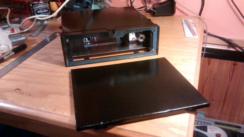
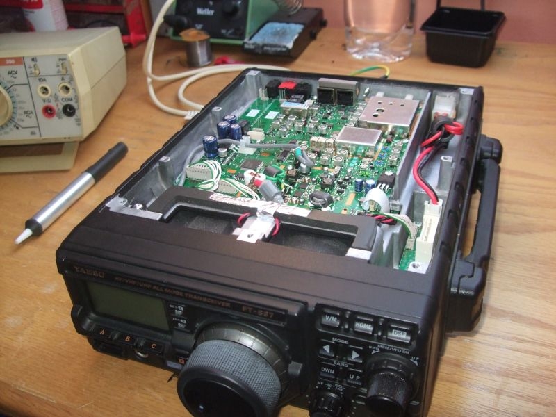
Here again with the lid off showing a better view of the top panel which is the one we are interested in.
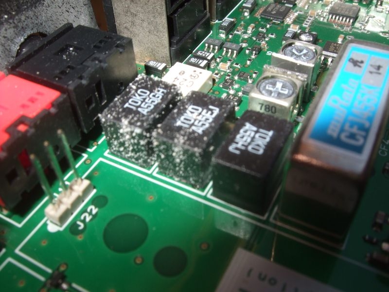
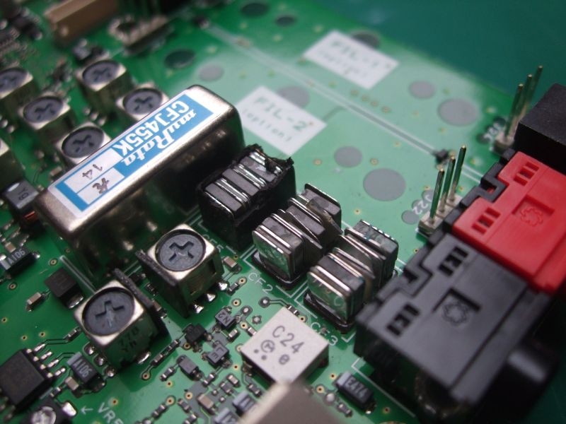
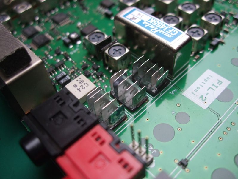
Here are the Ceramic IF Filters which are the cause of the insensitivity on the VHF bands, three filters in all for 6KHz, 9KHz and 12KHz. You can see the salts caused by moisture within the plastic encapsulation leeching to the surface. Two look to be severely damaged, the third looks reasonably OK. The moisture essentially destroys the insulation and corrodes the plates within the filters rendering them useless, severely attenuating the IF (Intermediate Frequency) stages of the receiver, these particular filters are only relevant to the VHF section of the receiver.
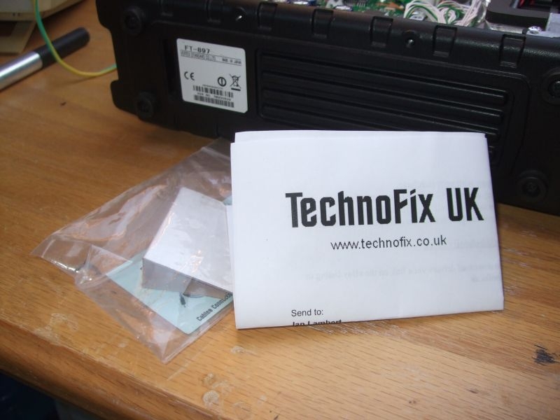
Here are the replacements that I got from Technofix via their Ebay shop, just realised I didn't take them out of the bag, I'll put a better picture up when I fit them.
I did not want to start proper disassembly until I had the anti-static matting and a proper earth environment to work from. Here is the mat it's 400 x 300mm and is a nice fit from front to back on the bench.
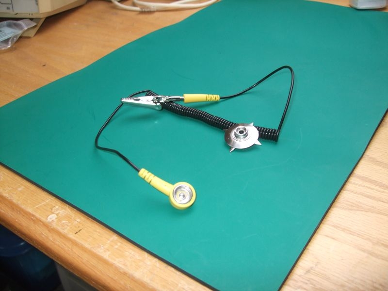
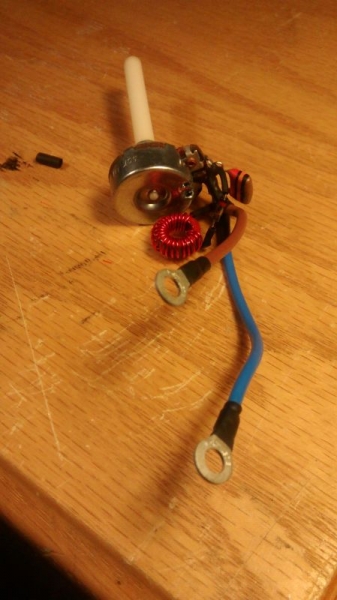
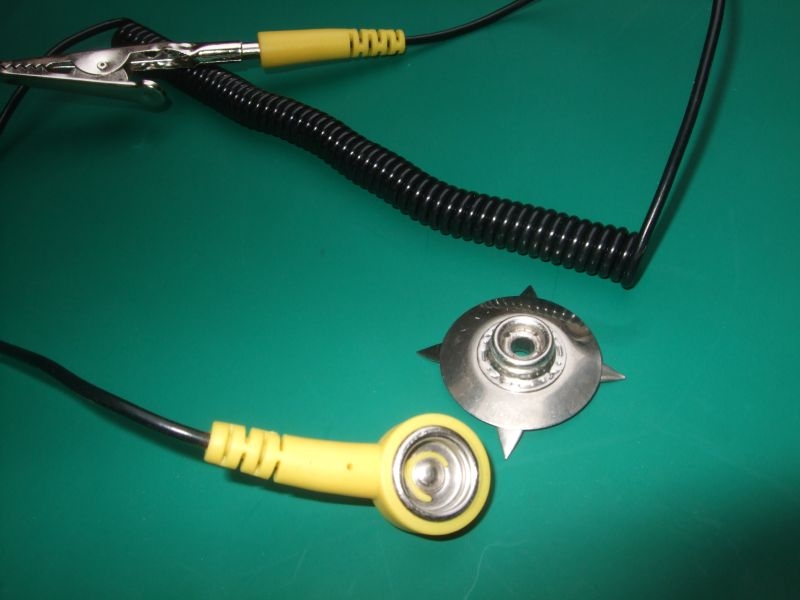
The mat is conductive rubber of some type, it's black on the back. The press stud connector is supplied loose so that you can fit it wherever you want on the mat, I connected mine in the back corner. The prongs are bent down and pushed through the mat from the top then opened up on the bottom effectively gripping both surfaces of the mat. Press stud, curly cable and crocodile clip to connect to your earthing point.
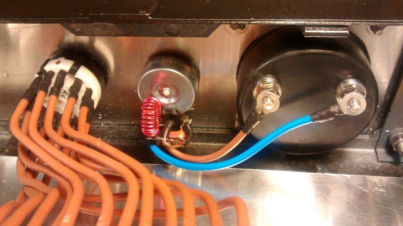
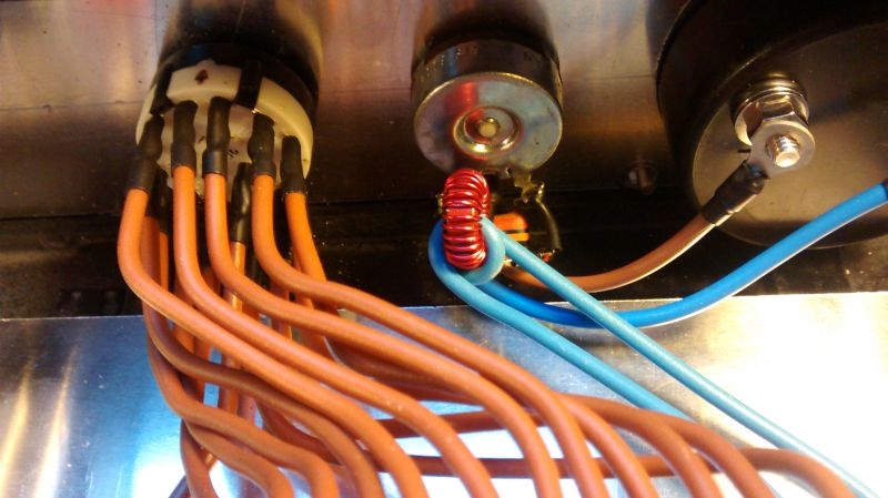
I have an earthing plug somewhere which is effectively a sealed plug with press studs on the back which are connected to the mains earth. Problem is I cant find it, it's probably in the same place as my original matting. Intermediate solution is a standard plug with a single wire from the earth pin running to a soldered on flat ring terminal. This is bolted directly to the earth terminal on the transceiver along with a wire loop to provide a common earth point, you can see that my wrist strap is connected here as well as the curly cable from the mat. Effectively the chassis on the transceiver is acting as a temporary bus bar for the system.
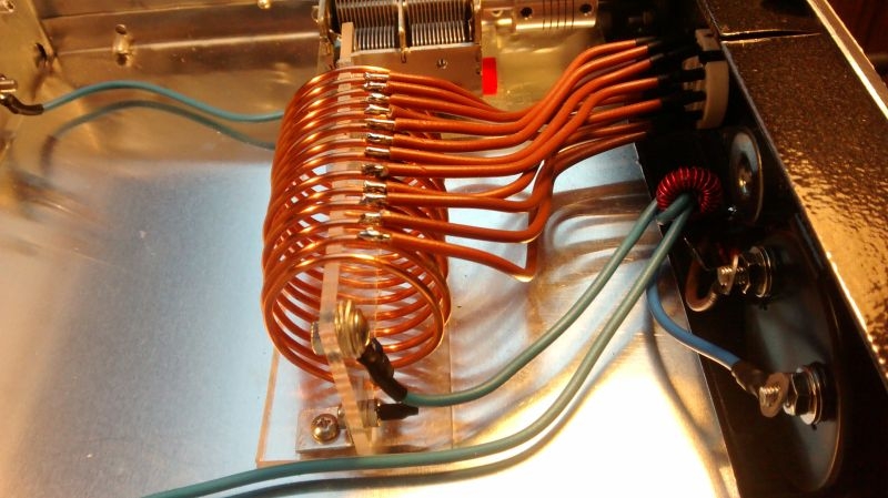
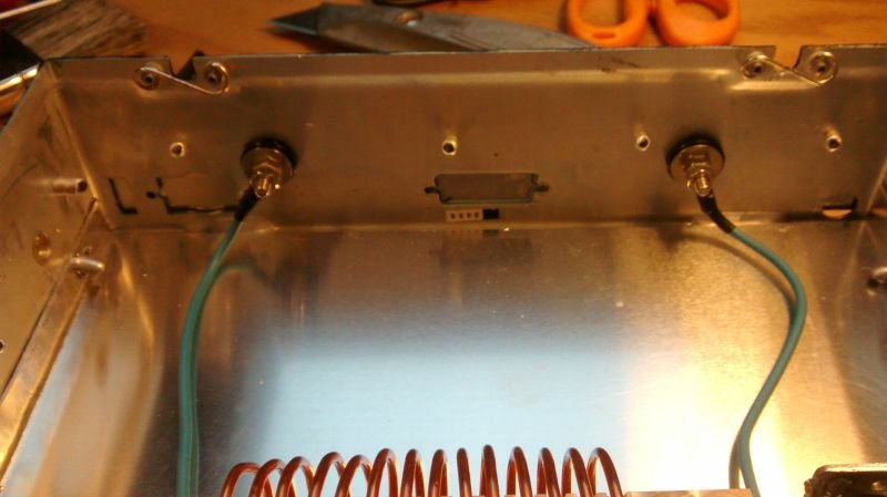
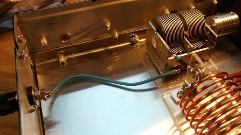
Once this was in place it was safe to remove the board. It is secured with about 12 machine screws around the edges and 4 more in the middle of the board a further 2 secure a couple of semiconductors mounted on the board to their cooling pads moulded on the chassis at each side of the board. A few connectors, a couple of miniature coaxial connectors and a ribbon lead disconnected and the board was out.
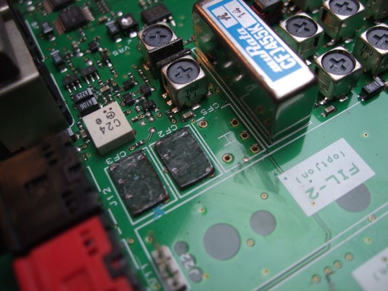
The recommended method of taking the filters out is to disassemble them from the top by breaking into the encapsulation and then removing the individual ceramic and mica insulation plates. Here they are with the tops off you can see how they are constructed with interleaved ceramic and dividing plates, these are sandwiched in between the plates that connect to the pins of the device
Carefully away with a jewellers screwdriver and a pair of tweezers and all the intermediary plates are out just leaving the connector plates and the bases.
As the plates are quite large in relation to the actual through board pins they will conduct a lot of heat away when trying to desolder so it is recommended that you snap the plates off from the pins below by gentle bending and twisting. This then allows you to remove the plastic base of the filter. This just leaves the pins which are soldered in plated through holes.
Later note.... this actually turned out to be bum information and caused untold grief with removal of the remnants of the pins and clearing the solder from the plated through holes.
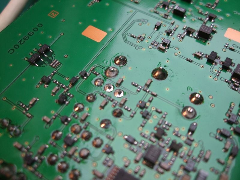
Here is the other side of the board showing a great number of surface mount components, many in very close proximity to the solder pads for the filter legs. To give some indication of scale the solder pads for through the board components are about 2mm, you can see that a lot of the surface mount components (the small rectangular blocks with silver ends) are much smaller than the pads so desoldering on the pads has to be done very carefully. It's a case of heating the target pad enough to remove the solder without overheating the adjacent surface mount components.
This where I ran into a problem I have a Weller digital soldering station that has bits down to 1mm but my smallest mini desoldering pump is too large to get into the pads properly. I have a complete Weller Vac desoldering station which also has bits down to 1mm but It had not seen the light of day for about 15 years. No real use for it when I gave up component level microprocessor repairs, I know also that the main desoldering head had been damaged in transit in my last equipment move.
Worth having a look though so I dug it out of the loft. It was as I had remembered, the head was physically damaged but it looked like nothing that could not be repaired with a bit of araldite. I plugged in the compressor base station and connected the head unit up. I has an electrical connection on a DIN plug and socket for the 24Vac feed and the temperature sensing feedback and a separate rubber pipe for connecting the head to the pump. The vacuum pump is started by a press button on the side of the handle and when operated the pump and it's pressure gauge operated without a problem. Trouble was the iron was stone cold regardless of the temperature setting. I pulled it apart suspecting that the damage to the head may have extended to the internal connection board for the thermostat, heating element and switch but that was not the case, the element itself is the problem. So I have an Vac desoldering station that sucks but won't get hot. I cant get an element for it as the head is now discontinued, I can get a replacement compatible head unit but it will cost me the best part of £150. I only want to desolder 9 holes! I may at some point look for a reasonably priced original replacement on Ebay.
In the short term I need a solution so to that end I have purchased a cheap combination desoldering tool. This consists of a 40W soldering Iron with an integral plunger desoldering pump built in.
The problem here is that the hole in the tip of this unit is HUGE, about 3mm in diameter and the tip itself too wide to do the job. I think I need the services of an engineering type bloke who could maybe modify the existing tip to allow me to use the 1mm tips from my £800 whiz bang desoldering kit which wont warm up?
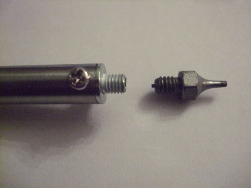
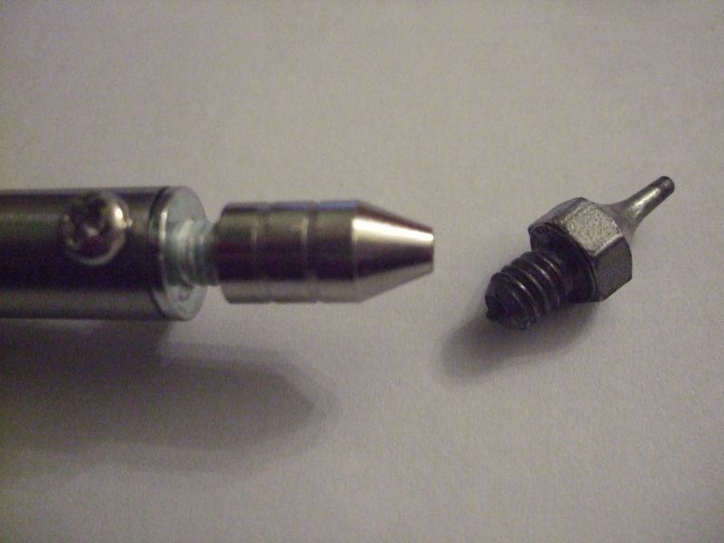
The end of the el cheapo iron screws out leaving a female on the bottom and a screw on the end of the iron, all the miniature tips from my other kit have screw connections with male threads on the bottom of them. It needs the cheapo tip modifying with a matching tapped hole in the end. This way I could attach any of the small tips I have to the cheapo iron, here it is in pictures.
Iron with partially screwed out tip and miniature vac tip
Or I need to attach this to this with a suitably tapped replacement connector, the threads are different on the iron and the mini tip.