A few posts ago I mentioned that I used to enter my homebrew projects in the annual construction contest that we ran at the Rolls Royce Amateur Radio Club. Here is the design that I won with after a previous years close second to an engineering project.
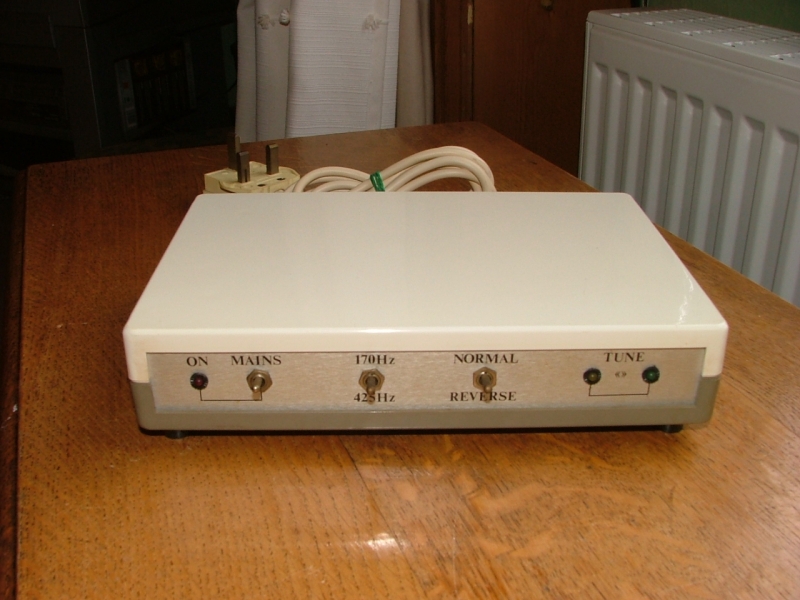
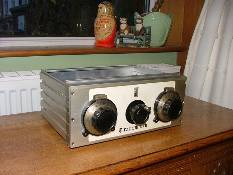
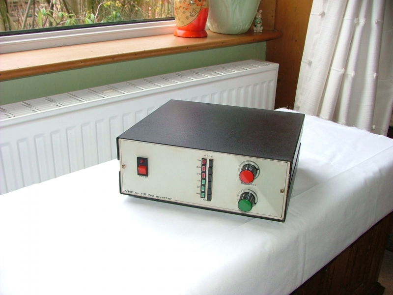
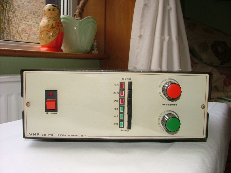
This is what is known as a Transverter and is used to enable a transceiver that is designed for one particular frequency band to operate on a completely different band or multiple bands. The first picture is a general view of the completed Transverter.
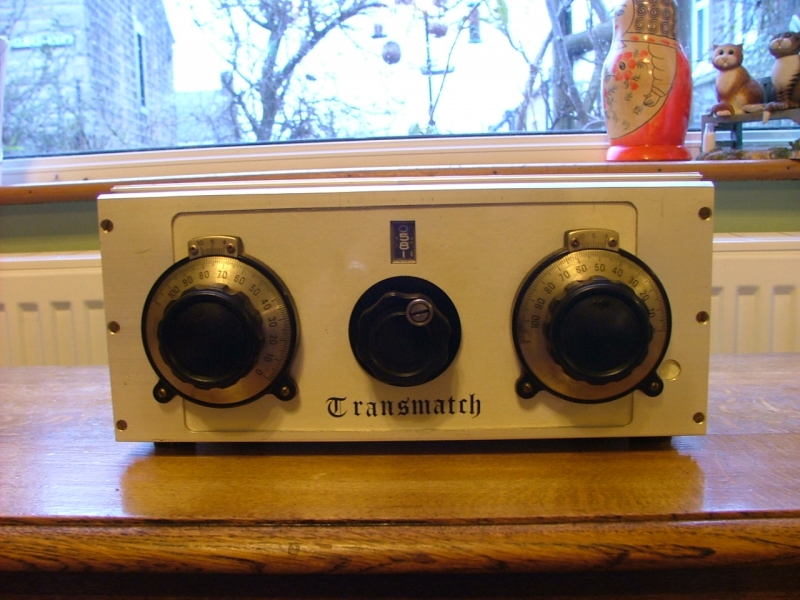
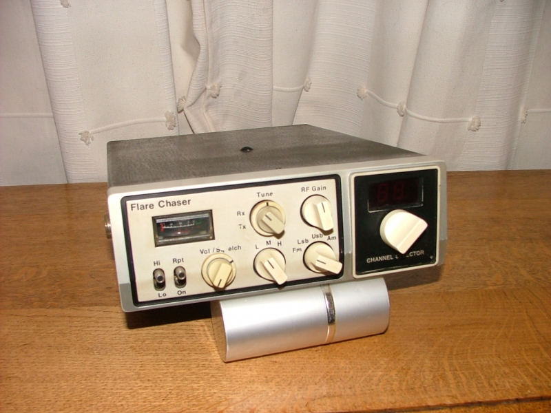
Here is a view of the front panel showing the very minimal controls (the fun is under the lid). There is the on/off switch, the band selector switch with six bands and a pre-selector control associated with each of three channels. You can see I colour coded the switches to co-ordinate with the relevant pre-selector control. I fitted a Perspex front to the aluminium fronted case to protect the annotating decals which were made using Letraset rub down lettering.
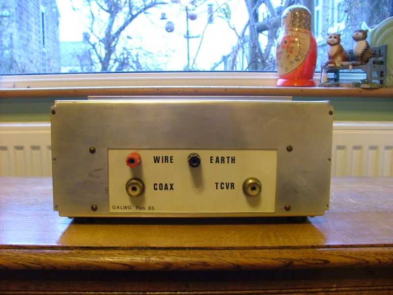
This is a view of the back of the case which is fitted with stand off's to space the connectors away from the wall. There are SO239 sockets for the connection from the driving transceiver and the antenna input/output from the transverter. A 2 pin DC input socket completes the connectors on the back. You can see that I annotated the unit with details of the design which came from one of the amateur radio magazines of the day. The transverter was featured across two monthly editions in August and December 1983 of Ham Radio Today. Each of the designs was for 3 band devices, the first article was for a transverter design covering the 1.8 MHz (160M), 3.5 MHz (80M) and 7.0 MHz (40m) bands and the later one covered the 14 MHz (20M), 21 MHz (15M) and 28 MHz (10M) bands. The original articles gave instructions for two complete units with 3 band coverage from each. I decided to adapt the design and put the whole lot in one box with modifications to the associated switching but ultimately producing a combination design that would give full coverage of all six of the main amateur HF bands from one unit.
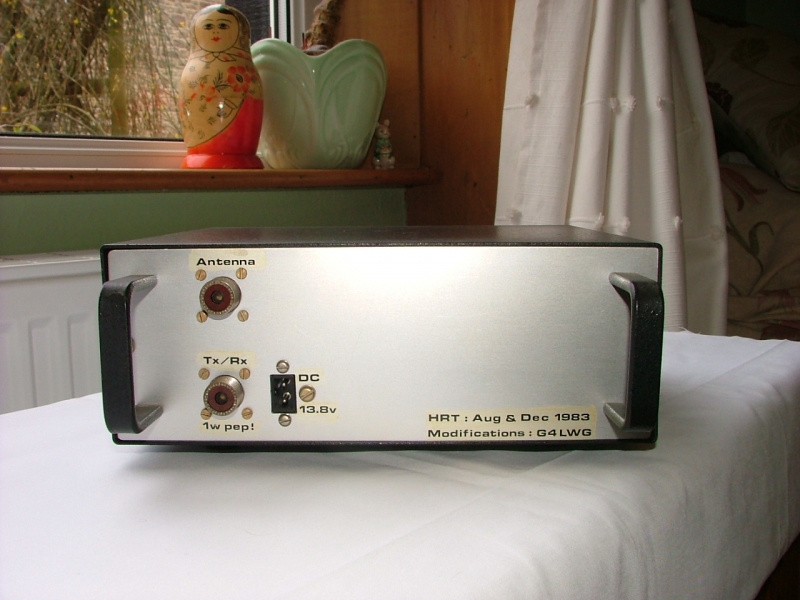
The transverter operates from VHF to HF and HF to VHF and interfaces with any low power 144 MHz (2m) transceiver. It converts the transmitted output from the VHF transceiver into the corresponding frequency on whatever HF band is selected.
For example: The 3.5 MHz amateur band (80M) covers 3.5 MHz – 3.8 MHz. To produce this range from the transverter the driving transceiver should be tuned from 144.5 MHz – 144.8 MHz to transmit on corresponding frequencies in the 80M band. Incoming signals on the 80M band will be transverted to their corresponding frequencies between 144.5 MHz – 144.8 MHz for reception on the transceiver.
In transmit mode it is converting downwards in frequency. On receive, it takes the incoming HF signal and converts it upwards in frequency, back to the 144 MHz band for reception on the drive transceiver. Input to the transverter should be limited to a maximum of 1W p.e.p (peak envelope power), it will produce the same power level at the transverter output, and this in turn can be used to feed into an HF linear amplifier to provide higher output power if required. The transverter will operate in any mode that the interfaced transceiver is capable of.
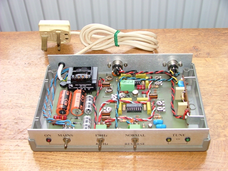
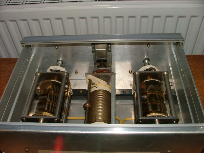
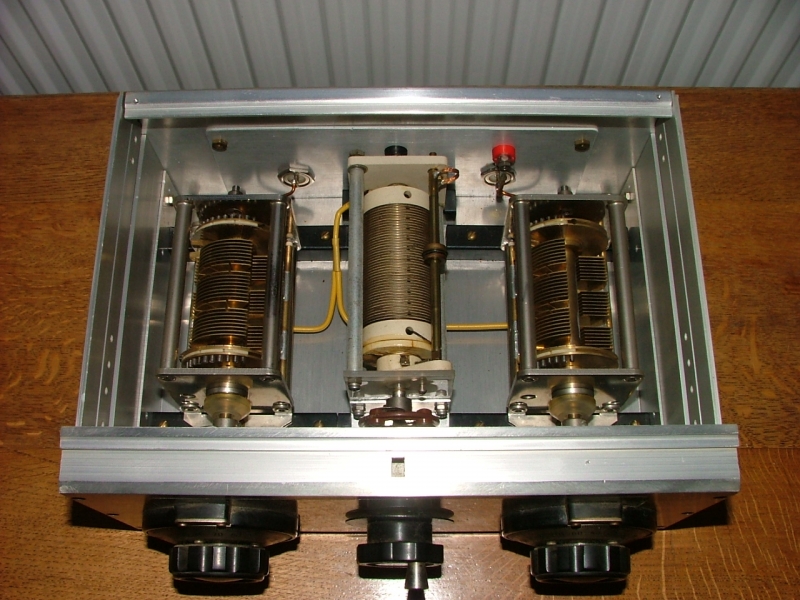
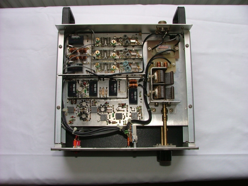
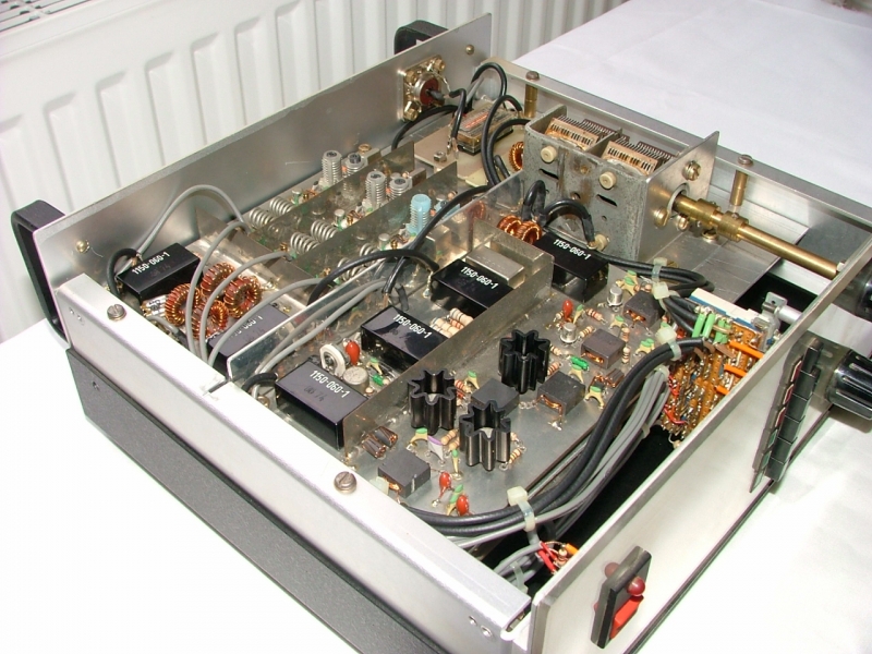
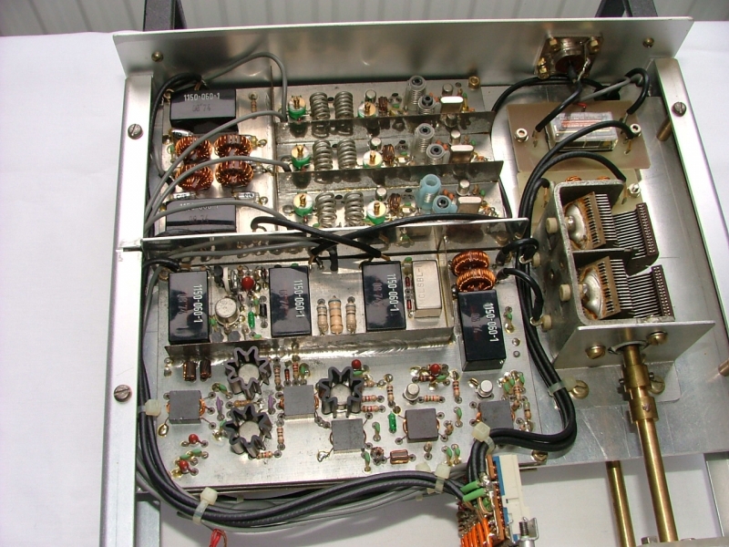
Here is the inside view with the top cover removed. I added a central shelf to the project case I selected for the design. This was to allow a mirrored layout arrangement. The pre-selector control is connected to a variable capacitor which in turn is connected to the board at the front which has the associated pre-selector circuitry; this effectively acts as a narrowband filter to the incoming HF band signals before passing them on to the Intermediate Frequency mixing stages on the same board. You can see that there are a number of relays on the board; these operate to switch in the correct oscillator frequencies for whichever band is selected (160M/80M/40M) by the front panel switching. The crystal oscillators for each band are situated on the board at the centre back of the unit. The small relay section at the top left operates to switch the transverter circuitry between transmit and receive modes.
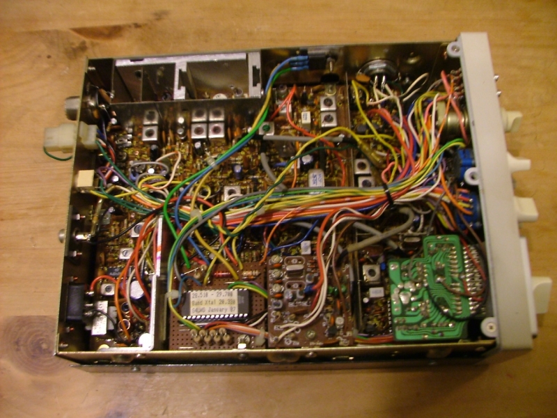
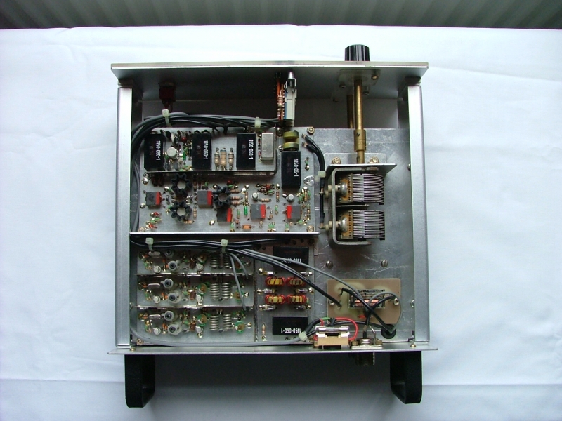
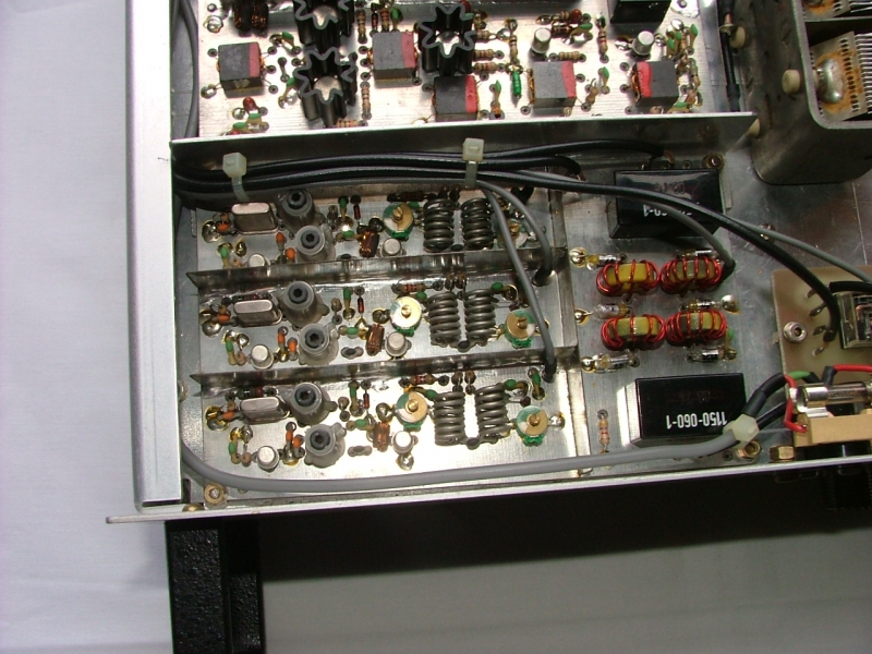
The next picture shows the underside of the unit where the boards are mounted on the reverse of the centre shelf. The boards on each side of the case use common mounting studs with spacers. This layout maintains a continuous ground plane within the unit. It is an exact copy of the top but the board circuitry and oscillators now cover the other three bands (20m/15M/10M). There are minor differences between some of the coil assemblies as they cover different frequencies.
The blank circuit boards were only available through the magazine for about a year. It was two years after the articles had been published when I decided to have a go at the project so boards were no longer available. I had all the equipment to produce the boards although I had never attempted a double sided ground plane board before. Fortunately the layouts were fully documented in the articles with 1:1 artwork. As this device operates at RF frequencies the boards are designed to minimise instability by removing as little of the copper as possible and so maintaining an effective ground plane for the various sections of the circuit. The boards are double sided with only feed through holes cleared on the top component side, any interconnecting circuit tracks on the reverse.
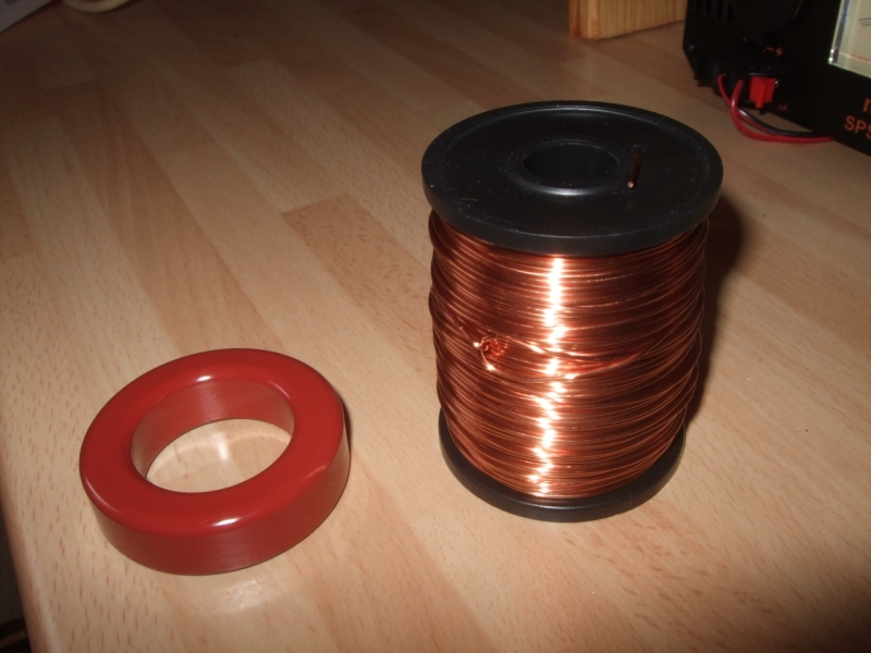
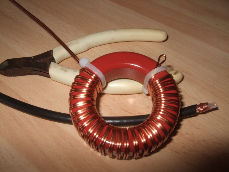
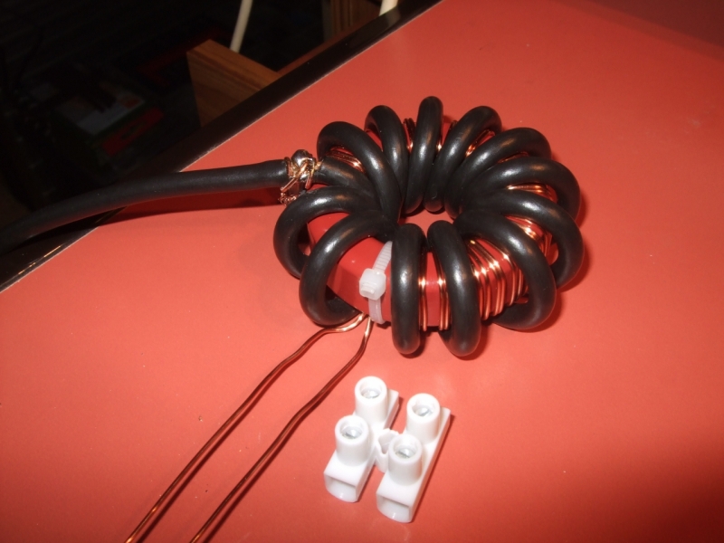
A few close up pictures to show various features. All of the wound toroid’s (the rings on edge), the coffin feed through ferrite's (square flat), the small bead ferrite's and the open coils were all hand wound. They are all wound with various gauges of enamelled copper wire. The toroid coils are varnished to hold them in place.
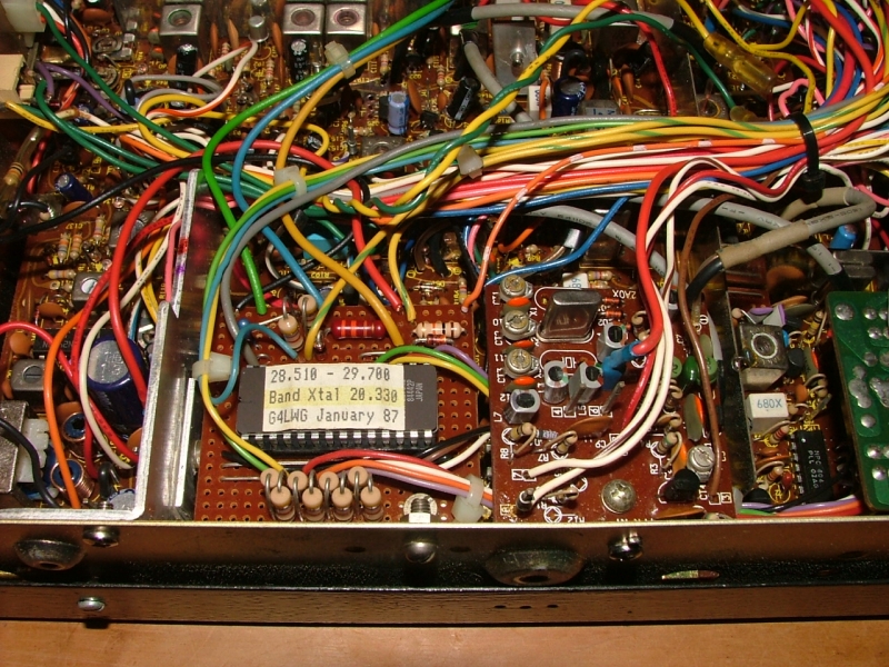
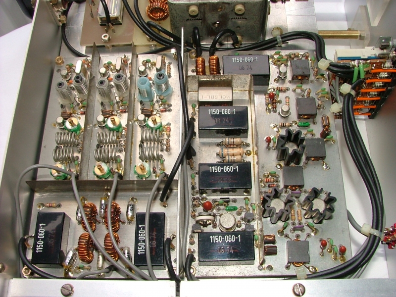
Here is a close up which mainly shows the crystal oscillator section. The tuning coils with the ferrite slugs were off the shelf types. The inter stage screening was produced from tin plate sections which were edge soldered to the ground plane on the boards. Screening is required to cut down cross modulation between the different sections of the design. The transistors on the mixer and RF output board are all fitted with heat sinks. Any interconnecting cables between boards use screened cables and are kept to minimum length.
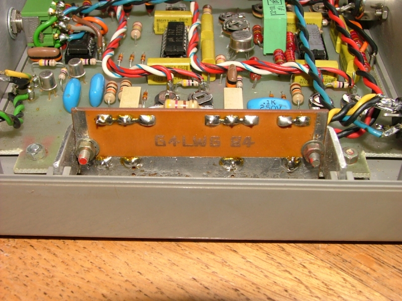
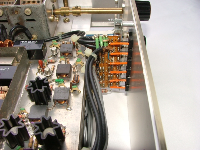
The next photo shows the front switching arrangement. The original design used a simple 3 position rotary switch for each transverter. I wanted to use push buttons so I had to develop a board that would support the interlinked 6 band switching arrangement. I mounted the interconnecting switches on Veroboard and then attached this to a right angle bracket for mounting. The Veroboard allowed me to create a common ground point for the array and bring out the shielded connecting cables neatly. The switches are mutually exclusive so you can only select one band at a time. They are break before make so it is impossible to cross drive the mixer and oscillator stages.
The last two pictures are close up views of the top side boards. It’s the first time in about 25 years that the covers have been off this unit and it still looks like the day I produced it.
It took 3 or 4 months to gather all the required parts together from various suppliers and amateur radio rallies. There are quite a few size critical components that cannot be substituted due to the board designs. Actual construction and alignment took a further 6 months or so steadily away. I think it cost about £70 - £80 for all the components back in the mid 1980’s. The cost of the time though cannot really be accounted for although it would almost certainly be in excess of what a commercial HF transceiver could be bought for at the time. That’s not the point though.
This effort represents the pinnacle of my home construction skills and designs. I had a lot of fun putting it together. It works very well and gives full 6 band HF coverage from a 2M low power multi-mode transceiver. I still have my multi-mode 144 MHz transceiver to drive this with so it will get another airing at some time in the future. I don't have an HF amplifier so I will see how far I can get with the bare 1W output.