Page 26 of 104
Re: STEAM ENGINES AND WATERWHEELS
Posted: 18 Apr 2014, 05:09
by Stanley

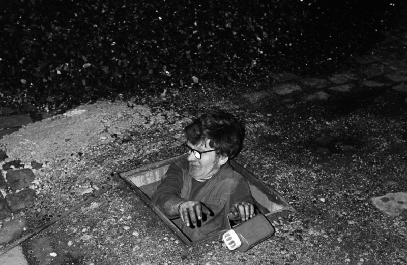
Another dirty but essential job. Cleaning the foot valve on the condenser water intake in the dam at Bancroft.
Re: STEAM ENGINES AND WATERWHEELS
Posted: 19 Apr 2014, 05:20
by Stanley
We were repairing a broken blow down pipe during the night to keep the mill going the following day. In this case John Plummer had drawn the short straw! We finished at 2AM and started on time the day after. None of the weavers suspected there had been a problem.
Re: STEAM ENGINES AND WATERWHEELS
Posted: 20 Apr 2014, 04:28
by Stanley
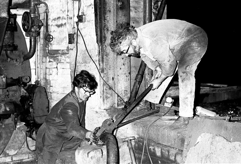
John Plummer and Stanley earning their money late at night to get the mill running the following morning. Daniel Meadows did the picture.
Re: STEAM ENGINES AND WATERWHEELS
Posted: 21 Apr 2014, 04:30
by Stanley
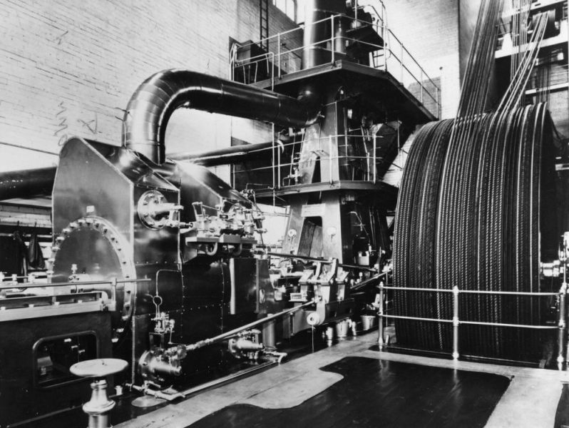
The engine at Fox Mill, Hollinwood. This was a Manhattan by George Saxon. The Manhattan engine was a combination of vertical and horizontal engines on the same shaft which took up less floor space. Named after the first designs installed to produce electricity in Manhattan, New York. (
LINK)
Re: STEAM ENGINES AND WATERWHEELS
Posted: 22 Apr 2014, 05:26
by Stanley
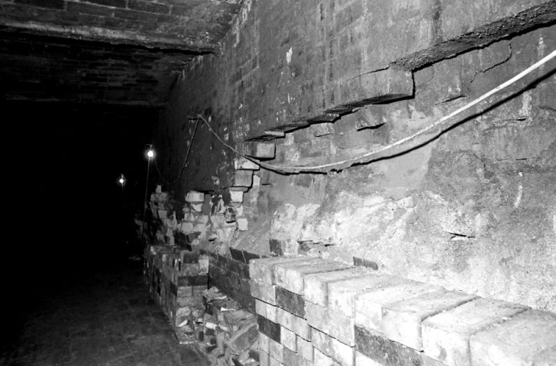
Not what you want to see in your flues. This was what confronted me when we got the Ellenroad flues cleaned out. Walls bulging and shattered and remember, they were the foundation walls for what was above. More to running engines than just using Brasso!
Re: STEAM ENGINES AND WATERWHEELS
Posted: 22 Apr 2014, 10:25
by Bodger
Stanley, an iteresting rebuild of a steam navvie
https://www.youtube.com/watch?v=Ug6hmnUvTps
Re: STEAM ENGINES AND WATERWHEELS
Posted: 22 Apr 2014, 10:55
by Bodger
Re: STEAM ENGINES AND WATERWHEELS
Posted: 23 Apr 2014, 04:43
by Stanley
I'll look at them later Bodge, late up this morning.
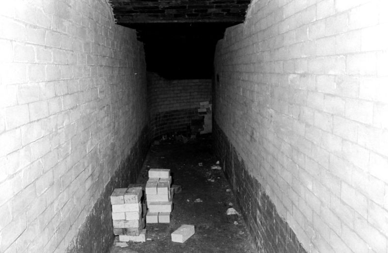
The flues after we had breathed on them. White bricks are Class 1 refractory, the lower red ones are common brick, all that's needed at low level where it is cooler and often protected with flue dust.
Re: STEAM ENGINES AND WATERWHEELS
Posted: 23 Apr 2014, 09:31
by Stanley
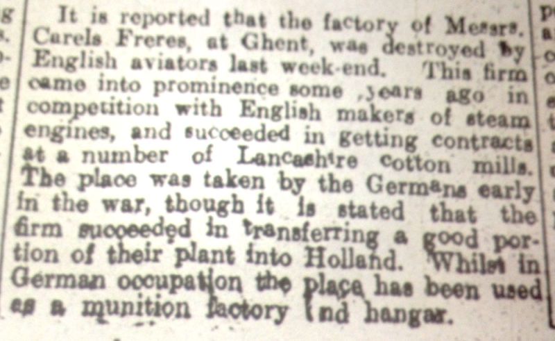
Here's an interesting item I tripped over on the web. 23 June 1917.
Re: STEAM ENGINES AND WATERWHEELS
Posted: 24 Apr 2014, 03:52
by Stanley
Mons at Todmorden was the biggest Carel Freres engine in Lancashire.
Re: STEAM ENGINES AND WATERWHEELS
Posted: 25 Apr 2014, 04:39
by Stanley
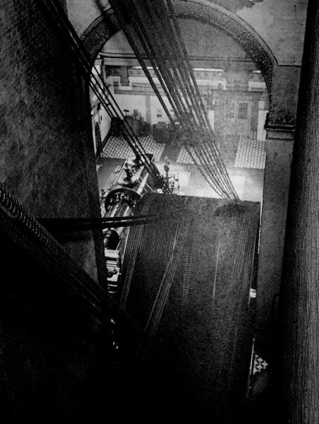
The rope race at Mons Mill. Remember that only half the mill was built which is why there are so few ropes. Newton saw it running and told the engineer it ran like a basket full of pots. He wasn't impressed.
Re: STEAM ENGINES AND WATERWHEELS
Posted: 26 Apr 2014, 06:43
by Stanley
I have goodies for you this morning, John Burlison has been busy!
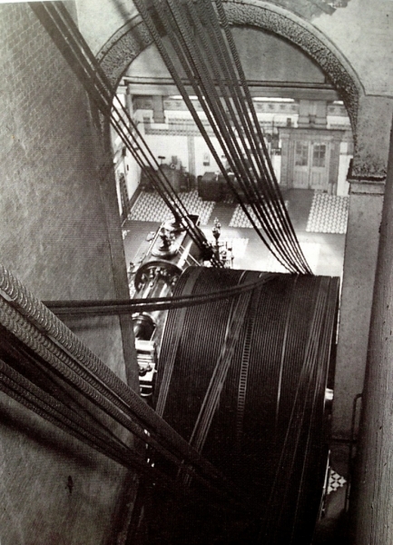
First, a better image of the Mons Mill rope race.
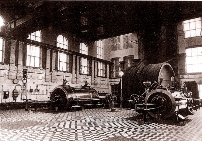
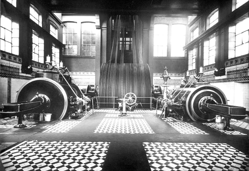
This is Butts Mill at Leigh. A smaller version of the Mons Carel Freres engine.
Butts Mill, Leigh -
“Carel Freres” (Belgium) 2,500 h.p. cross compound engine, 66 r.p.m. 25ft 9" dia flywheel 54-ropes, 5 “Tinker-Shenton” (Hyde) boilers. a very similar layout engine room as Mons Mill.
1600 hp right handed, tandem compound engine by Carel Freres, Ghent, order
number 875, 1909. 30"HP, 53"LP X 4 ft stroke. 160 psi, 90 rpm. 21 ft flywheel, 62 tons, ? ropes. Drop valves on both cylinders. Airpump driven from crank pin. Tail rod support guide. This engine was originally going to be a twin tandem. Crank and trunk guide casting on the left.
[Watkins records: Moston Mill, Moston, Nr Manchester. Cotton Spinning. Intended to be a double mill eventually, Moston was built with the crankshaft, and flywheel for the full power, and provided with the bed for the other half the engine upon which the outer end of the crankshaft ran. Built by Carels Brothers, Ghent, Belgium in 1909, it was their works no 875, with cylinders 30 and 53 bore by 3 ft 11 1⁄4 in stroke. Developing 1,200 hp at 90 rpm, superheated steam 200 psi was supplied by Tetlow boilers. The flywheel, 19 ft in diameter, was provided with the sixty rope grooves that the full power would have required. The second half of the mill, however, was never completed, and in 1958 electric drives were installed, and the engine was scrapped. Typical of Continent design, six or more of Carels' engines were installed in Lancashire mills in the early 20th century.]
Re: STEAM ENGINES AND WATERWHEELS
Posted: 27 Apr 2014, 05:11
by Stanley
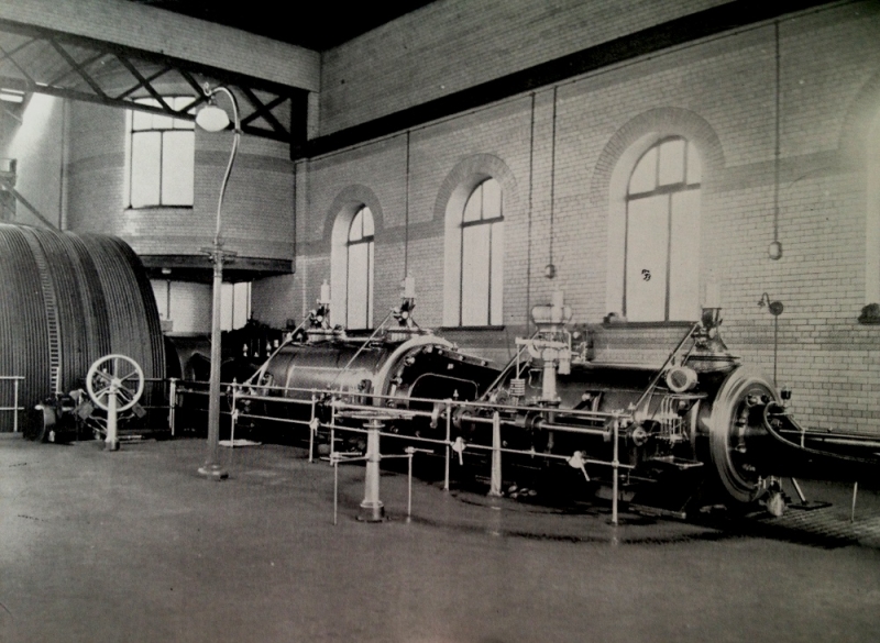
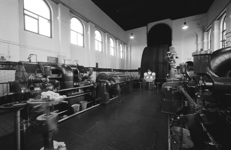
I was thinking about the Moston Mill engine. If the other side had been built it would have been a similar size to Ellenroad in its modified form but a far cleaner and more modern design. At 90rpm it ran far faster than Ellenroad at 55rpm. A very modern design for 1909 and to my mind better than our home grown engine makers were doing. Compare it with one side of Ellenroad.
Re: STEAM ENGINES AND WATERWHEELS
Posted: 27 Apr 2014, 07:47
by plaques
Stanley. Something obvious to you perhaps, but how did they tension the driving belts so that they were all taking their part of the load?
Re: STEAM ENGINES AND WATERWHEELS
Posted: 27 Apr 2014, 08:40
by Stanley
Good question P. The load a rope transmitted was governed by what it was driving and there was enough contact with the driving wheel to make sure that it had enough grip. Ideally a rope drive was always set up with the idle side of the drive at the top and the ropes in tension beneath the wheel. Any spare rope sagged in a catenary curve which in itself increased the area of contact with the driving wheel. When fitted new the ropes were of a length which meant they were tensioned at the top but as they wore they stretched slightly and sagged but it was no problem. That was one of the major skills of the rope splicers, stretching the rope before splicing and getting the length exactly right. They would never tell you how they worked it out, I think that most was down to experience. If you want to delve deeper, the best source is the 1907 edition of 'An Epitome of Lectures on the Transmission of Power by Ropes' published by Willem Kenyon and Sons, Chapel Field Works, Dukinfield who were major manufacturers and rope drive engineers.
Re: STEAM ENGINES AND WATERWHEELS
Posted: 27 Apr 2014, 10:12
by chinatyke
I enjoy reading about these monsters. To think it is only a century ago that these were state of the art power generators. Massive engineering, 70 ton flywheels, multiple steam raising boilers, and the skilled people needed to operate and produce them, just to get a few hundred HP.
Nowadays electric motors are so compact. At my last place of employment we had 3 x 333 kW motors driving compressors to provide cooling for a chemical process, that's about 1340 HP in one little (noisy) room. Remote starting all handled electronically and automatically. I think some conveyor belts in the mining industry must have huge power demands.
That's progress I suppose but still so good to see and read about the old engineering equipment and achievements. Thanks Stanley for sharing your experiences with us.

Re: STEAM ENGINES AND WATERWHEELS
Posted: 28 Apr 2014, 04:22
by Stanley
It's a pleasure China. Don't forget that a good steam engine and boiler is still better thermal efficiency than an electric motor. Even if you factor in capital cost the sums still add up. There is the added bonus that you have better control, Bancroft ran through all the power cuts and was only stopped during the government three day week even though we had coal stock in the yard. Think of using mains electricity as outsourcing and you have a perfect analogy with governments outsourcing responsibility by privatising and then losing control of costs and sometimes, availability.
In industries like cane sugar and sugar beet you have the added advantage where the waste from the process can be burnt as fuel. Think of straw burning traction and portable engines. At Ellenroad I put up a scheme for the engine to be used to generate electricity of the site and sale to the grid. Coates did a full investigation and came to the conclusion it was not only viable but profitable. However, they decided not to go down that route and didn't give a reason. I think it was the responsibility factor that killed it.
Re: STEAM ENGINES AND WATERWHEELS
Posted: 29 Apr 2014, 04:21
by Stanley
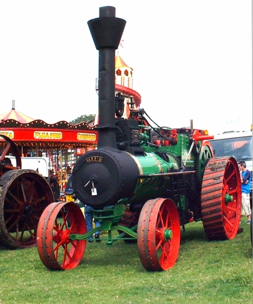
John Ingoe's Paxman engine was a straw burner originally destined for Argentina but never sent because previous engines weren't paid for. The quick way to identify a straw-burner is a large firebox, big tubes (usually 3") and a small hole in the side of the firebox protected by a cover that can be used to poke a rod in and knock 'bird's nests' off the tube plate where they gather on the ends of the tubes cutting down on the draught.
Re: STEAM ENGINES AND WATERWHEELS
Posted: 30 Apr 2014, 06:35
by Stanley
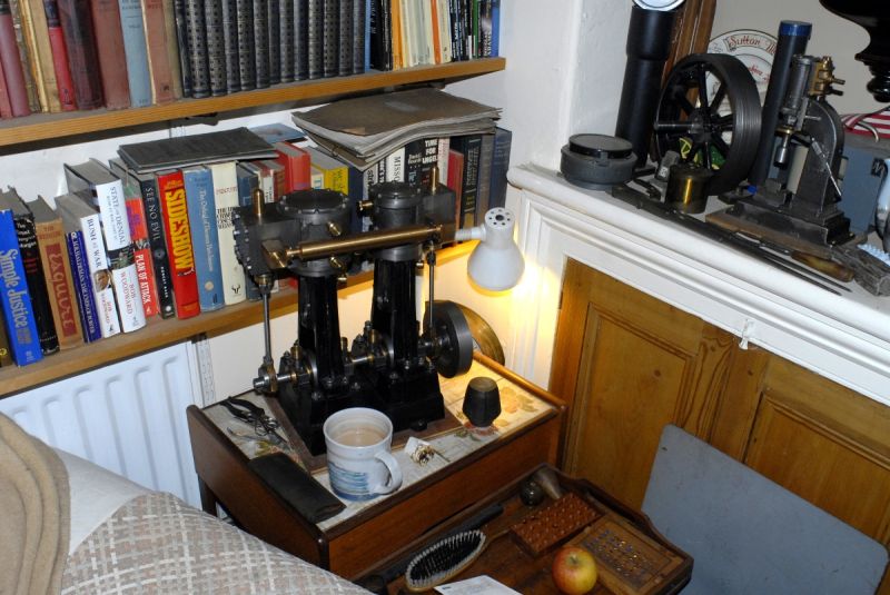
I've spent a lot of time with the full size engines but even so it was amazing how much I learned by building working models. The sequence of machining and building is exactly what the original engine manufacturers had to go through.
Re: STEAM ENGINES AND WATERWHEELS
Posted: 01 May 2014, 04:54
by Stanley
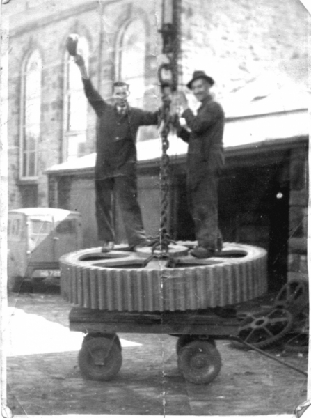
Newton Pickles and Leslie Green stood on the new casting for the second motion pinion for Bishop House Mill. This had just been delivered. It was cast By Roberts at Nelson and was out of true. 1947. They weren't quite so cheerful when they got the casting into the lathe and found the defects. Roberts were in a bad way and couldn't afford to re-cast the pinion so Johnny and Newton did the best they could to rectify it but it never ran well.
Re: STEAM ENGINES AND WATERWHEELS
Posted: 01 May 2014, 08:22
by Bodger
Stanley, re multiple rope drive, when replacing a rope did they have a "stretcher" to hold the two ends wilst they made the splice ?, i know where i worked when replacing the main drive flat belt to the line shaft the two ends were held and pulled together via a mechanical adjuster untll the joint was made.
Re: STEAM ENGINES AND WATERWHEELS
Posted: 02 May 2014, 05:56
by Stanley
No Bodge, the splice was made with the rope off the wheel and then barred on afterwards. This was why the formula they used to determine the length of the rope before splicing was so important. The new rope was almost bowstring tight but soon relaxed during use. Getting this right was the skill of the splicers.
Re: STEAM ENGINES AND WATERWHEELS
Posted: 02 May 2014, 07:50
by Bodger
I take it then that if the dodgy rope was in the middle of the race wheel they moved all the ropes on that floor level so that the replacement was at the end otherwise they would have to feed the new rope under all the others ?
Re: STEAM ENGINES AND WATERWHEELS
Posted: 02 May 2014, 08:13
by Stanley
No, they moved it across the top of the other ropes by using wedges and blocks to force it over while the engine was barred over.
Re: STEAM ENGINES AND WATERWHEELS
Posted: 03 May 2014, 06:34
by Stanley
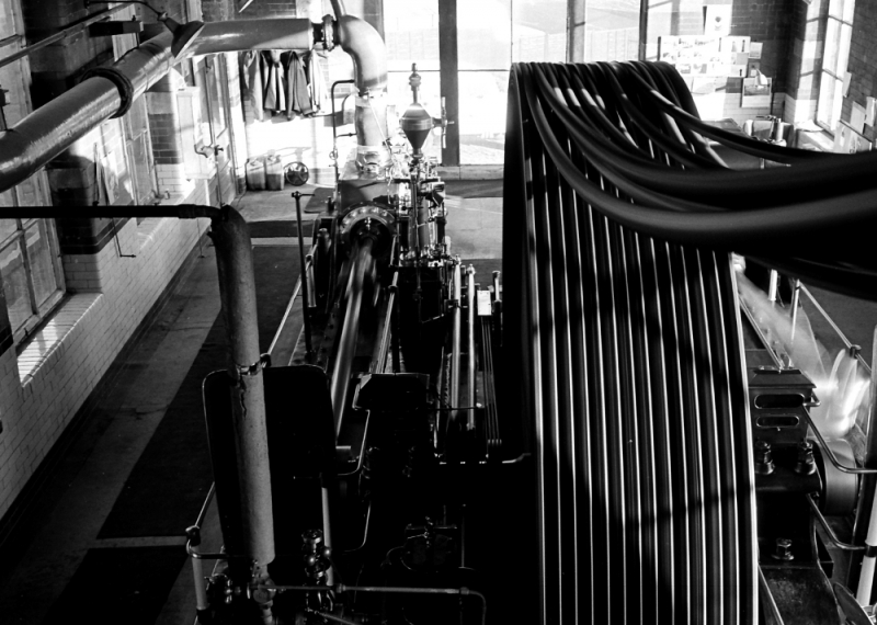
The rope drive at Bancroft under load in 1976. You can see that not all the ropes are bearing equal tension or indeed exactly the same length. I improved matters by dressing them with rope grease over a few months. This was a mixture of tallow and graphite and whilst in theory it reduces grip slightly on the wheels, in practice it evens the grip out on all of them and they run much more efficiently. Most of these ropes are the originals from 1919.